
User manual

PmodTPH2™ Reference Manual
Copyright Digilent, Inc. All rights reserved.
Other product and company names mentioned may be trademarks of their respective owners.
Page 2 of 2
Header J1
Pin
Signal
Description
Pin
Signal
Description
1
1
Pass through #1
7
7
Pass through #7
2
2
Pass through #2
8
8
Pass through #8
3
3
Pass through #3
9
9
Pass through #9
4
4
Pass through #4
10
10
Pass through #10
5
5
Pass through #5
11
11
Pass through #11
6
6
Pass through #6
12
12
Pass through #12
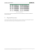
Table 1. Pinout description table.
Any external power applied to the PmodTPH2 must be able to be handled by your two pieces of hardware on
either side of the Pmod.
3 Physical Dimenions
The pins on the pin header are spaced 100 mil apart. The PCB is 2 inches long on the sides parallel to the pins on
the pin header and 0.8 inches long on the sides perpendicular to the pin header.