
Instruction Manual

Digilent, Inc.
FX2 MIB Reference Manual
www.digilentinc.com
www.digilentinc.com page 4 of 4
Copyright Digilent, Inc. All rights reserved. Other product and company names mentioned may be trademarks of their respective owners.
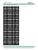
Table 2 Pmod Connector Pin Layouts
J1 Top Set of Pins
Pin Pinout
1 IO1
2 IO3
3 IO5
4 IO7
5 GND
6 VDD
J2 Top Set of Pins
Pin Pinout
1 IO9
2 IO11
3 IO13
4 IO15
5 GND
6 VDD
J3 Top Set of Pins
Pin Pinout
1 IO17
2 IO19
3 IO21
4 IO23
5 GND
6 VDD
J4 Top Set of Pins
Pin Pinout
1 IO25
2 IO27
3 IO29
4 IO31
5 GND
6 VDD
J5 Pins
Pin Pinout
1 IO33
2 IO34
3 IO35
4 IO36
5 GND
6 VDD
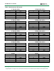
J1 Bottom Set of Pins
Pin Pinout
7 IO2
8 IO4
9 IO6
10 IO8
11 GND
12 VDD
J2 Bottom Set of Pins
Pin Pinout
7 IO10
8 IO12
9 IO14
10 IO16
11 GND
12 VDD
J3 Bottom Set of Pins
Pin Pinout
7 IO18
8 IO20
9 IO22
10 IO24
11 GND
12 VDD
J4 Bottom Set of Pins
Pin Pinout
7 IO26
8 IO28
9 IO30
10 IO32
11 GND
12 VDD
J6 Pins
Pin Pinout
1 IO37
2 IO38
3 IO39
4 IO40
5 GND
6 VDD