
User manual
3.JumperOptions
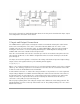
Several jumpers are used to configure or control the operation of the Digilent VRM:
Jumper J2 is used to select the output voltage. Install a shorting block on J2 to select 3.3V output.
Otherwise the voltage output is 5V.
Connector J5 allows access to the enable input to the regulator. This allows an external controller,
(such as a microcontroller) to turn the regulator on or off. Driving the EN pin on this connector to
ground will turn off the regulator. Allowing this pin to float will turn the regulator on. The pin can also
be used to provide an undervoltage lockout. Refer to the data sheet for the TPS54620 for more
information.
Connector J8 can be used to provide an external clock signal to control the switching frequency of
the regulator. Connecting the CLK pin on J8 to an external clock will cause the VRM’s switching
supply to synchronize to the external clock source. The external clock must be a square wave
between 200kHz and 1600kHz. The amplitude of this signal must transition below 0.8V and above
2.0V. If the CLK pin is left disconnected, the supply will switch at 479kHz.
Connector J7 provides access to the PGOOD signal out of the regulator. The PGOOD pin on J7
provides the status of the VRM output voltage. This pin floats during normal operation. The pin is
driven low to indicate a power supply fault. This occurs when the VRM’s reference voltage is below
91% or above 109% of normal. The PGOOD pin should be connected to a pull-up resistor to avoid
erroneous fault detection.
https://reference.digilentinc.com/vrm/refmanual11‐10‐17