
User manual
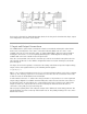

Refer to the schematic for detailed information about the circuitry on the board and the input, output,
and configuration connections on the board.
2.InputandOutputConnections
The VRM board has power inputs and outputs in both screw terminal and two-pin header format.
Connect the external power source to the connections labeled “GND” and “VU” on the screw
terminal connector J6, or the two-pin header, J3, labeled “BATTERY”. Observe proper polarity in
making the connections, as reversed polarity will damage the VRM. Digilent has battery packs
available with connectors suitable for the two-pin header.
Note: the screw terminal connector J6 is rated for up to 10A of current but the two pin header J3 is
only rated for 2A. Do not use the VRM in configurations where more than 2A of input current will
pass through J3.
The input current to the regulator is a function of the voltage ratio between input and output voltage,
output current, and regulator efficiency. The following formula applies:
I
i
= ((V
o
/V
i
) * I
o
) /e
Where: I
i
& I
o
are input and output current, V
i
& V
o
are input and output voltage, and e is the regulator
efficiency. The efficiency depends on several factors, but a value of 0.9 is reasonable. Refer to the
TI data sheet for the TPS54620 for more information.
Screw terminal connector, J1, and the three two-pin headers of J4 provide access to the regulated
output voltage. Digilent has available two-wire MTE power cables that are ideal for connections to
the two-pin headers. As noted above, the screw terminal connector is rated for up to 10A, but the
two pins headers are only rated for 2A each. Do not attempt to draw more than 2A on these
connectors as they will get very hot and may fail.
Observe proper polarity when connecting the outputs of the VRM to the circuit being powered. The
polarity markings for J4 are on the top of the board near J4. The polarity markings for J1 are on the
bottom of the board.