
Operating instructions


4 - 42
MAN0443.P65 Issue 13 Aug 04 5701 Control System
05701-M-5001 A02279
CHAPTER 4 - INSTALLATION INSTRUCTIONS
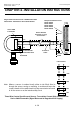
Three Wire Control Card Current Sink, Transmitter Current Source Connection for
Searchline Excel (Signal Returned to 0V)
Note: 1. Where a sensor is earthed locally, either to the Earth Stud or
through the sensor casing or mounting, to avoid earth loops
the screen sheath of the cable should only be connected at
one end. ie. At the sensor or at the Interface/relay Card.
2. The Searchline Excel analogue output is non isolated and is
factory configured as current sink or current source.
Connector and link settings are shown for current source
model only, contact Zellweger Analytics for other option.
Single Channel Control Card 4 - 20mA 05701-A-0301
Fitted with 4 - 20mA Sensor Drive 05701-A-0283
4
4
1
1
GND
ORANGE A
+24V DC Supply
BLACK 0V
WHITE 4-20mA
BLUE B
0V DC Supply
4-20mA Output
GRN/YEL GND
RED 24V
35
36
33
34
31
32
29
30
27
28
25
26
23
24
21
22
19
20
17
18
15
16
13
14
11
12
9
10
7
8
5
6
3
4
1
2
Relay/Field Interface Card
05701-A-0326
05701-A-0327
05701-A-0328
05701-A-0329
05701-A-0330
Arrows Indicate
Direction of Loop
Current Flow
Screened Cable
Cabinet
28
29
27
NS
S
01
Protective
Earth
(Instrument
or Clean
Earth)
Searchline Excel Receiver
Current Source
Connections using a
DVC100 Junction Box
LK3
LK12
LK10
LK7
Link Positions
Receiver Connections
1
4
TB2
TB1
4
1
Earth
Terminal
Earth
Instrument Earth
Cable
Shield
ORANGE A
0V DC Supply Rx (0V)
IS EARTH IS EARTH
BLACK 0V
WHITE 4-20mA
RED +24V
BLUE B
4-20mA Output Rx (SIG)
GRN/YEL GND
+24V DC Supply Rx (+24V)
Control Cabinet
Connections
Connections using a
DX100 Junction Box