
Operating instructions


4 - 40
MAN0443.P65 Issue 13 Aug 04 5701 Control System
05701-M-5001 A02279
CHAPTER 4 - INSTALLATION INSTRUCTIONS
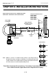
Three Wire Control Card Current Source, Transmitter Current Sink Connection for
Searchpoint Optima (Signal Returned to Regulated +23V Supply)
+24V
4 - 20mA
0V
GND
-
Earth
Terminal
Terminal
Block
Junction
Box
Arrows Indicate
Direction of Loop
Current Flow
Green/Yellow - Ground
Black - 0V DC Supply
White - 4 - 20mA Output
Red - +24V Supply
Blue Communications
Orange Link to SHC1
SHC1
Searchpoint Optima
(Configured for current
sink using hybrid
module 04200-A-0145)
Screened
Cable
S
01
NS
Cabinet
Protective
Earth
Note: 1. Where a sensor is earthed locally, either to the Earth Stud or
through the sensor casing or mounting, to avoid earth loops
the screen sheath of the cable should only be connected at
one end. ie. At the sensor or at the Interface/relay Card.
2. The Optima analogue output is non isolated and is factory
configured as current sink or current source. The actual
configuration is identified by a label on the Optima white
4 - 20mA output lead.
Single Channel Control Card 4 - 20mA 05701-A-0301
Fitted with 4 - 20mA Sensor Drive 05701-A-0283
Relay/Field Interface Card
05701-A-0326
05701-A-0327
05701-A-0328
05701-A-0329
05701-A-0330
28
29
Link Positions
27
LK3
LK1
LK12
LK9
LK6