INSTALLATION MANUAL 6609-2221 Galvanic Isolation Transient Protection Balanced Transmission ED-20 PPP ROU TER Serial In terface PPP Router Rurstraße 4 D-41564 Kaarst 1 Telefon (02131) 6 69 08-0 Telefax (02131) 66 71 48 Internet: www.digicomm.de e-mail: info@digicomm.de CE Approved © Westermo Teleindustri AB • 2003 • REV.
Contents 1. Safety .................................................................................................................................................................................. 2. Approvals ....................................................................................................................................................................... 2.1 Declaration of Conformity ...................................................................................................
1. Safety ! General: Before using this unit, read this manual completely and gather all information on the unit. Make sure that you understand it fully. Check that your application does not exceed the safe operating specifications for this unit. ! Before installation, maintenance or modification work: Prevent damage to internal electronics from electrostatic discharges (ESD) by discharging your body to a grounding point (e.g. use of wrist strap).
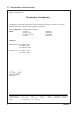
2.1 Declaration of Conformity Westermo Teleindustri AB Declaration of conformity The Westermo Teleindustri AB company declares that the listed products conforms to the Council Directive 89/336/EEC, related to Electro Magnetic Compability.
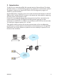
3. Introduction The ED-20 is an industrialised DIN Rail mounted, serial to Ethernet Router.The device will allow access to a remote Ethernet network via a Westermo communication product. The device is easily set-up using the ED-Tool for ED-20 configuration program via TELNET or serial connection. Standard PPP dial-up networking tools can be used from Microsoft Windows 9x, ME, NT, 2000 or XP, Or another ED-20 to connect to the device. Any other platform supporting the PPP protocol could equally be used.
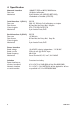
4. Specification Network Interface Data rate Mechanical 10BASE-T. IEEE std 802.3, 2000 Edition. 10 Mbit/s, half duplex. RJ-45 Modular Jack (ISO/IEC 8877:1992), Unshielded or shielded (UTP/STP). Serial Interface 1 (CH 1) Data rate Data format Control signals Mechanical RS-232 300–115 200 bit/s Full, half duplex or simplex. 8 Data Bits, No Parity Bit,1 Stop Bit RTS, CTS, DSR, DCD, DTR 9-pin female D-sub, DCE.
Transient Protection Network Interface Serial Interface Power Interface ±4 kV, EN 61 000-4-5:1995 Class 4 ±2 kV, EN 61 000-4-5:1995 Class 3 ±0.5 kV, EN 61 000-4-5:1995 Class 1 Application Throughput (maximum) Network protocols Serial/Network conversion 115 kbit/s (1.44 MB data) TCP, IP, ARP, ICMP,Telnet Configuration Remotely over network or locally at serial interface. Windows based PC-programme.
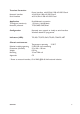
5. Maintenance No maintenance is required, as long as the unit is used as intended within the specified conditions. 6. Installation 6.1 Mounting /Removal ! Before mounting or removing the unit: Prevent damage to internal electronics from electrostatic discharges (ESD) by discharging your body to a grounding point (e.g. use of wrist strap). Prevent access to hazardous voltages by disconnecting the unit from AC/DC mains supply and all other electrical connections.
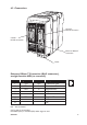
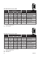
6.2 Connections Cannel 2: RS-232 connection Cannel 1: RS-232 connection ED-20 PPP ROU TER Serial In terface Ethernet 10Base-T connection Power Ethernet 10Base-T Connection (RJ-45 connector), straight function MDI (no crossover) Contact 1 2 3 4 5 6 7 8 Signal Name TD+ TD– RD+ Direction** Out Out In RD– In Description Transmitted Data Transmitted Data Received Data NC NC Received Data NC NC 8 7 6 5 4 3 2 1 ** Direction relative ED-20 NC Not connected CAT 5 cable is recomended.
1 2 3 4 5 6 7 8 9 CH1: RS-232 Connections, DCE Pin Number 1 2 3 4 5 6 7 8 9 * ** NC Signal Name* Description V.24 RS-232C DCD 109 CF RD 104 BB TD 103 BA DTR 108.
6.3 LED Indicators From left to right. CH1:TD LED off LED on CH1: RD LED off LED on CH1: RTS LED off LED on CH1: CTS LED off LED on PWR LED off LED on CH2:TD LED off LED on CH2: RD LED off LED on CONFIG LED on LED off NET LED off LED on LED flashing 6609-2221 Transmitted Data (incoming serial data): • RS-232 TD =1, Mark (<–3V). • RS-232 TD =0, Space (>3V). Received Data (outgoing serial data): • RS-232 RD =1, Mark (<–3V). • RS-232 RD =0, Space (>3V). Request To Send: • RS-232 RTS =Off (<–3V).
6.4 DIP Switch Settings DIP-switches are accessible under the lid on top of the unit. Prevent damage to internal electronics from electrostatic discharges (ESD) by discharging your body to a grounding point (e.g. use of wrist strap), before the lid on top of the modem is removed. ! Warning! Do not open connected equipment. Prevent access to hazardous voltages by disconnecting the unit from AC/DC mains supply and all other electrical connections.
6.4.1 MAC address The MAC address of the unit can be found on the product label “00 30 56 F” + last 5 digits on IC2 see figure in section 6.4 Switch settings on page 12. Example: Label on IC2 “SC12 RTOS 0092C2” this will give the unit MAC address “00 30 56 F0 92 C2” The MAC address can also be find out with the DOS command “ARP –a”. (Perform the “PING” command with the ED-10 local IP address before the ARP command.) 6.
7. Functional description The ED-20 can be in either configuration mode or in application mode. Normally the ED-20 is in application mode, where the serial-to-network data transfer is enabled and all configuration settings are readable. Change of configuration parameters are done in ED-20 configuration mode. Configurable parameters are listed in chapter 6.3. 7.1 Application mode In application mode the ED-20 transfers data between the serial interface (CH1) and the network interface (10BaseT).
7.1.2.2 PPP connection The PPP connection can be established over PSTN, Leased Line or private lines. ED-20 can act as a PPP Server, PPP Client or both.These functions is set on the ‘Modem settings’ tab in ED-Tool for ED-20. See application example on page 30. Connections can be established in several ways depending on the application: • Standard PPP dial-up networking tool. • ‘Connect’ command on CH2: or via TELNET • Using the ‘Brouter’ function. 7.1.2.
8. Configuration Before read, write or reboot can be made, Select type of connection: • Network • Serial com port must be selected from menu ‘Tools – Serial COM Port’ 8.1 Configuration by ED-Tool for ED-20 This section describes the configuration of the ED-20 with the software ED-Tool for ED-20. Program Start: To start ED-Tool for ED-20 • Locate ED-Tool under Program on the Start-Menu.
8.1.1 ED-Tool for ED-20 commands This section describes the ED-Tool for ED-20 commands. The commands are described by there use. Details about allowed values and default values is described is section 6.2. 1 2 57600 3 RTS/CTS 4 5 6 8.1.1.1 General commands 1 2 Read Config 3 Write Config 4 Reboot Selects type of connection, Serial or over the Network. If ‘Serial’ is selected, use the “Tools menu – Serial COM port” to select which of COM1:, COM2:, COM3:, or COM4: your serial cable is connected to.
PSTN AT&F&DOSO ATH DIAL IN/OUT OK OK NO 3 3 NO 1 1 ATDS=0 RING CONNECT ATA 60 0 +++ 1 2 3 4 5 6 7 2 600 1 8.1.1.3 Modem Settings General 1 Modem Connection 2 Dial IN/OUT 3 Connect at PWR On 4 DCD Control* 5 Escape Sequence 6 Escape Delay 7 Idle Time 18 Select Type of connection, PSTN or LL. • Use PSTN for dial-up connections, e.g. Phone modem, GSM modem or ISDN adapter. • Use LL for fixed connections, e.g. LeasedLine-, Radio-, Fibreor any Short-haul- modem.
Modem AT-Commands Refer to the user guide or installation manual to the attached modem. 1 2 3 4 5 6 7 8 Modem Init 8 Command 9 Answer 10 Timeout 11 Retries Modem Hangup 12 Command 13 Answer 14 Timeout 15 Retries AT&F&DOSO ATH OK OK 3 3 1 1 ATDS=0 RING CONNECT ATA 60 0 16 17 18 19 20 21 22 1 Set the modem init string, max string length:25 characters. Set the expected answer from the modem on the command string. Note! Modem result codes must be enabled.
NONE ed20 **** 1 2 169.254.200.100 169.254.100.100 3 169.254.200.101 255.255.255. 0 4 5 6 7 8 255.255.255. 0 8.1.1.4 Network Settings Login 1 Authentication 2 Username 3 Password Select if authentication shall be used or not. Set the login username. This is also used for Telnet sessions (Network configuration). Set the login password This is also used for Telnet sessions (Network configuration). PPP Network Interface* 4 Local IP Set the Server IP address.
1 . . . 2 3 4 5 6 8.1.1.5 Brouter Settings Brouter Mode 1 Off / On Brouter Settings 2 IP Address 3 Connect Message 4 Add >> 5 Remove … 6 Disables or enables the Brouter mode. See 8.2.4 Set the target IP address that shall initiate a connection. Set the Connect message that shall be sent to the attached modem. E.g. ATDnnnnnn Adds the values IP Address and Connect message to the brouter entry list Remove marked entry from entry list.
1 . . . 2 3 4 5 8.1.1.6 Firewall Settings Firewall Mode 1 Off / Pass / Block Disables or enables the Firewall mode and selects if the firewall shall work in Block or Pass mode. See 8.2.5 Firewall Settings 2 IP Address 3 Add>> 4 Remove … 5 22 Set the source and destination IP addresses that shall be allowed to pass through the ED-20, or set the source or destination IP addresses that shall be blocked from passing through the ED-20.
8.2 Configurable parameters 8.2.1 Serial interface Communication Data Rate The data rate can be set from 1 200 bit/s to 115.2 kbit/s. Allowed values: 1 200, 2 400, 4 800, 7 200, 9 600, 14 400, 16 000, 19 200, 38 400, 56 000, 57 600 and 115 200 bit/s. Default: 57 600 bit/s. Flow Control Flow control can be chosen between none or RTS/CTS. If the RTS/CTS being used then the cable must have all interconnecting wires between the ED-20 and the modem connected and the modem shall have the flow control enabled.
Dial IN/OUT Select the operating mode of the ED-20. -Dial IN, The unit will act as an PPP Server and only accept incoming calls. Modem Connect (Dial OUT) and the Brouter function will be disabled. -Dial IN/OUT, The unit will act both as an PPP Server and an PPP Client. When an incoming call is detected then the PPP Client is disabled. –Dial OUT, The unit will act as an PPP Client and not accept incoming calls. Modem Connect (Dial IN) and the function Connect at PWR on will be disabled.
Escape Sequence When communication is established with another modem it is still possible to reach the command mode by sending an escape sequence to the modem. Note! Refer to the user guide or installation manual to the attached modem. Default: +++ Escape Delay Define the delay time in seconds after the escape sequence been sent until the next AT-command will be sent.
Modem Hangup Command Hangup string that will be sent to the modem. Default: ATH Answer Expected answer from the modem on the sent command. Default: OK Timeout Define the time in seconds between the sent command and the expected answer before the command have failed. Allowed values: 0 to 9999 Default: 3 Retries Define the number of retries in case if a failed command. Allowed values: 0 to 9999 Default: 1 Modem Connect (Dial Out) Command Dial out string that will be sent to the modem.
Answer Command that will answer the incoming call. Default: ATA Timeout Define the time in seconds, For how long time the ED-20 will accept incoming calls from power-up. Normally not used, leave as is. Allowed values: 0-9999 Default: 0 8.2.3 Network Settings Login The login username and password is used on the dial-in connection and when the ED-20 is configured with ED-Tool for ED-20 over a network connection. Authentication Select if authentication shall be used over the PPP link or not.
PPP Network Interface These values is used when the ED-20 is in Server mode. The server will provide the IP addresses for the PPP link. Note! When connecting to a private remote network via the ED-20 using Windows network connection wizard, Always Obtain an IP address automatically Local IP* When the ED-20 is in server mode, this will be the Servers IP address on the PPP link Note! The Network ID must be different than the Network ID on the remote network and the Network ID locally.
8.2.4 Brouter settings The brouter function will initiate outgoing connections. This function is only available in PSTN + Dial Out mode (Refer to section 8.2.2 – General – Modem settings and Dial IN/OUT.) When a IP packet sent to the ED-20 have a IP Address that match a IP Address in the entry list, the ED-20 will send the connect message to the attached modem.This will result in an connection to another location and establishment of a PPP link.
9. Application examples Example of application with IP address settings. Remote connection – LAN (Dial In) 169.254.200.100 169.254.100.100 169.254.200.101 255.255.255. 0 IP: 169.254.100.101 GW: 169.254.100.100 255.255.255. 0 PLC PSTN LAN ED-20 PPP ROUTER Serial Interface ED-20 IP: 169.254.100.102 GW: 169.254.100.100 TD-33 TD-33 Remote connection PSTN PLC DIAL IN NO NO +++ LAN – LAN (Leased Line) IP: 179.254.100.101 GW: 179.254.100.100 169.254.200.100 179.254.100.100 169.254.200.
LAN – LAN (PSTN, Brouter, Firewall) IP: 179.254.100.101 GW: 179.254.100.100 169.254.200.100 179.254.100.100 169.254.200.101 255.255.255. 0 255.255.255. 0 PLC LAN ED-20 PPP ROUTER Serial Interface TD-34 ED-20 IP: 179.254.100.102 GW: 179.254.100.100 PLC 169.254.100.101 ATDnnnnnn 169.254.100.101 ATDnnnnnn PSTN 169.254.200.100 169.254.100.100 169.254.200.101 255.255.255. 0 IP: 169.254.100.101 GW: 169.254.100.100 255.255.255.
03.06 Mälartryck AB, Eskilstuna, Sweden T03-0376 6609-2221 Rurstraße 4 D-41564 Kaarst 1 Telefon (02131) 6 69 08-0 Telefax (02131) 66 71 48 Internet: www.digicomm.de e-mail: info@digicomm.