
User`s guide


HDSL
GENERAL
1.2
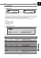
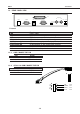
1.3. REAR PANEL VIEW
TX RX
G703 75
Ω
120 / 75
Ω
G703 120
Ω
V.35
LINECONFIGPWR
Picture 3
Name Function
PWR Power supply
CONFIG 9pin female connector for device configuration
LINE HDSL line connector RJ11 4 contacts
G.703 120 ohm G.703 interface 120 ohm 9 pin female connector
120/75 ohm switch G.703 interface setup at 120 ohm or 75 ohm
G.703 75 ohm TX G.703 interface 75 ohm coaxial BNC (send)
G.703 75 ohm RX G.703 interface 75 ohm coaxial BNC (receive)
G.703 75 ohm switch Join the shield of coaxial connectors G.703 75 ohm
V.35 V.35 interface, 25 pin female connector
1.3.1. LINE CONNECTOR PIN
PIN Signal
3 and 4 HDSL Line 1
1 and 2 HDSL Line 2
1.3.2. G.703 120 OHM CONNECTOR PIN
PIN Signal
1 and 2 Receive
4 and 5 Send
n.c.
n.c.
B A
BA
1B
2B
5B
6B
1A
2A
5A
6A
RED
BROWN
WHITE
BLUE
PIN2
PIN1
PIN3
PIN4
4 3 2 1