
User`s guide


HDSL
GENERAL
1.1
1. GENERAL
1.1. DESCRIPTION
TX
RX
G.703/V35
MASTER
TX
RX
G.703/V35
SLAVE
HDSL line 2/4 wires
R
HIGH SPEED MODEM
K1
K2
/G703
T/SLV
P
LOC
M REM
PW
LIN
LIN
V35
MS
LOO
ALM
AL
HDSL
R
HIGH SPEED MODEM
K1
K2
/G703
T/SLV
P
LOC
M REM
PW
LIN
LIN
V35
MS
LOO
ALM
AL
HDSL
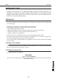
Picture 1
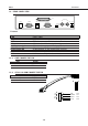
The connection is carried out using 2 HDSL devices: one placed in the main centre (Master)
and the other one in the remote place (Slave). The Master and Slave devices have different
configurations but are equal as for the electric or mechanic features.
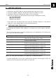
All the digicom’s HDSL modems are supplied with the following factory configuration:
l Master
l V.35 selected interface
l Two wires connection
l 256 Kbit/s line speed
l Internal clock
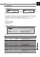
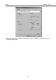
1.2. FRONT PANEL VIEW
R
HIGH SPEED MODEM
K1
K2
/G703
T/SLV
P
LOC
M REM
PW
LIN
LIN
V35
MS
LOO
ALM
AL
HDSL
Picture 2
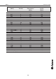
Name Color Condition Function
PWR Green Off No power supply
LINK1 Red On Channel 1 Status: Connected with the remote one
Flashing Channel 1 Status: Searching
LINK2 Red On Channel 2 Status: Connected with the remote one
Flashing Channel 2 Status: Searching
Off Channel 2 Status: disabled
V35/G703 Red On V.35 interface selection
Off G.703 interface selection
MST/SLV Red On Device configured as Master
Off Device configured as Slave
LOOP Red On Local Loop enabled
Flashing Loop enabled on the remote device
ALM LOC Red On Problem with G.703 interface
Flashing Fault on the local device
ALM REM Red On Problem with the G.703 remote interface (managed
on Master device only)
Flashing Fault on the remote device