
Specifications


15
Wiring (Continued)
1. Use minimum 18-gauge AWG thermostat wire for the 24vac control circuits. The load on these
circuits must not exceed 1 amp. The voltage range on R and C must not exceed 28vac. Check
Polarity before applying the transformer wire to R and C. Refer to the Polarity Check diagram
on Page 17.
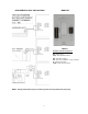
2. Connect the communication wires to the RX TX terminals. There are 2 sets of RX TX terminals
for “daisy chain” installation of this circuit. The communication wire specification is twisted pair
(Belden 8740) or shielded twisted pair wire (Belden 8450).
NOTE: When using shielded twisted pair wire (Belden 8450), just connect the shield conductors
together, as there is no electrical connection on the thermostat base terminals. The shield will be
landed on the GEN II controller on the G or TR2 terminal.
DIGICOM
Fig. 1
DIGIHP
Fig. 2
Blower Fan Relay
For electrical heat applications, which require a fan output on a call for heat, see Fig. 3.
Fig. 3