
Specifications


7
General Installation Instructions
GEN II Controller
1. Install the GEN II controller on an interior wall where the ambient temperature is between 32°-
120°F (0°- 48°C) non-condensing. This controller is to be installed in an accessible interior
area; not in attics or above ceilings.
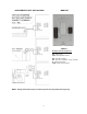
2. The controller is to be powered by a dedicated 24vac 40va transformer.
The transformer secondary is wired to TR1 TR2 on the controller (G).
The secondary voltage to the controller must be 24 to 28vac.
3. Install the LAT air sensor in the supply air between the indoor coil and electric strip heat
elements.
4. The leaving air sensor (LAT) is calibrated to the controller at the factory. However, the
calibration should be checked as part of the system setup procedures. If adjustments are
required, use the Blue potentiometer labeled R44 located in the upper left hand corner of the
GEN II controller. Screw the pot clockwise to lower the display temperature and counter -
clockwise to raise the temperature. NOTE: The display will update every 10 seconds.
5. Confirm you have connected the RX TX communication wires and R and C from the
thermostats to the controller (F&K), F = (R C), K = (TX RX). (Communication wire maximum is
4,000 ft. from the Command Center to the farthest ModStat, DIGICOM or DIGIHP.)
6. Connect the output wires from the controller to the HVAC system using standard 18 ga.
thermostat wire.
The LAT sensor leads may be extended using standard 18/2 thermostat wire.
Heat Pump operation “O” reversing valve
Cool Call – When a majority active cool call is received by the GEN II controller, Y1, O/B and G
LEDs are illuminated; and the outputs are energized (within 1.5 to 3 minutes). After 3 minutes, if
the leaving air temperature is 58°F (14°C) or above, Y2 will energize for 2-stage systems. If the
supply air temperature drops one degree below the Cool cut-out temperature, Y1 and Y2 will de-
energize for 4 minutes.
“B” reversing valve – Sequence of operation is the same: O/B is energized in the heat mode.
Heat Call - When a majority active heat call is received by the GEN II controller, Y1 and G LEDs are
illuminated; and the outputs are energized (within 1.5 to 3 minutes). If after 3 minutes the leaving
air temperature is 94°F (34°C) or less, Y2 will energize. If after 6 minutes of run time the leaving air
temperature is 91°F (32°C) or less, W2 will energize. If the supply air temperature exceeds 126°F
(52°C), Y1, Y2 and W2 (if energized) will drop out; and Y1 can then energize after a 4-minute time
delay. NOTE: If the system fan is configured for “AUTO” on the GEN II controller, the “G” output
will be de-energized in the temperature cut-out mode.
When the last active call satisfies, the GEN II controller goes into a 5-minute purge cycle with all
supply dampers closing; then all dampers modulate open for ventilation.
Emergency Heat - The GEN II emergency heat operation can be selected from any ModStat for
the entire control system. When the system operation mode is changed to Emergency Heat on a
given ModStat, the GEN II controller will recognize the mode change on the next system poll. The
thermostat which was used to select Emergency Heat does not have to make a heat call for the
GEN II controller to respond to the change. Once the GEN II controller changes the mode to
Emergency Heat, any ModStat in the system can make an emergency heat call. When the
controller receives a heat call in this mode, the compressor(s) are locked out and W2 is energized.
The GEN II controller will continue to make consecutive Emergency Heat calls until the ModStat(s)
have been changed back to the AUTO or HEAT mode.