SD5 Operation Manual User Manual - Getting Started To be read in conjunction with the SD Series Software Reference User Manual Version C for Software Versions 2.0.
SD5 Operation Manual Copyright © 2014 Digico UK Ltd All rights reserved. No part of this publication may be reproduced, transmitted, transcribed, stored in a retrieval system, or translated into any language in any form by any means without the written permission of Digico UK Ltd. Information in this manual is subject to change without notice, and does not represent a commitment on the part of the vendor.
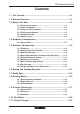
SD5 Operation Manual Contents 1.1 The Console ............................................................................. .......1-1 1.2 Manual Overview ..................................................................... .......1-1 1.3 Before You Start ....................................................................... .......1-2 1.3.1 Worksurface Layout ...................................................... .......1-2 1.3.2 Layers and Banks .........................................................
SD5 Operation Manual 1.12 Multi-channel formats.......................................................... .......1-22 1.13 Solo Setup............................................................................. .......
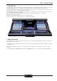
SD5 - Getting Started 1.1 The Console The Digico SD5 consists of a worksurface, an audio engine and a range of onboard inputs and outputs. This can be connected to multiple Input/Output Rack Units by optical fibre and/or MADI links, which carry all the audio input and output signals. The console worksurface consists of 3 sections that can be configured to control up to 124 input channels, 24 VCAs, 56 busses plus a Master buss (Up to 5.1) and 24 Matrix Inputs and Outputs.
SD5 - Getting Started 1.3 Before You Start There are certain general operating principles and terms that should be understood before continuing to use this manual. Please read this chapter carefully before proceeding. 1.3.1 Worksurface Layout..............................................................
SD5 - Getting Started 1.3.2 Layers and Banks ................................................................. The SD5's worksurface is divided into Layers and Banks. Each Bank contains twelve channels, and the channels which are currently active on the control surface are defined using the fader bank and bank layer buttons to the right of the Channel Strip section’s faders: A ‘bank’ is a set of twelve faders, and a ‘layer’ contains up to five ‘banks’.
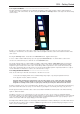
SD5 - Getting Started Pop-ups are closed by pressing the box in the top right-hand corner of the pop-up, marked CLOSE or CANCEL (or by pressing CAN on keypad pop-ups). To the right of the Centre Panel is a single encoder marked Touch-Turn (shown below). This is used to access any rotary controls within the Master Screen. To assign the Touch-Turn encoder to a particular on-screen pot, touch the pot to be assigned.
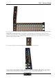
SD5 - Getting Started The 2 rows of twelve encoders and buttons immediately below the touchscreen (shown above) refer to the channels with which they are aligned. Pressing one of the Quick Select buttons on the left of the screen will assign the selected function to the top row of these controls below the screen. Six aux sends can be displayed in the Channel Strip panel at any one time.
SD5 - Getting Started To the left of the Channel Strip panel are more channel controls: When pressed, the 2nd function button allows access to different parameters: 1) Stereo Aux Pan and Pre/Post switching 2) Hard Mute of a channel 3) Switching of LR or LCR panning 4) Fine adjustment of Delay settings on output channels 2nd function is indicated by a green 2nd Function display appearing in the bottom left-hand corner of the screen, as well as by the 2nd function button lighting with a ring of green.
SD5 - Getting Started 1.4 Hardware Configuration 1.4.1 Connections .......................................................................... Detailed information on the various systems of connection is provided in the relevant chapter of this manual but the following diagram provides an overview of a single console/single rack setup.
SD5 - Getting Started 1.5 Software Configuration The SD5 has a default setup which means that the new user need not get involved in configuring the desk at this stage. However, here is a brief overview of how the different displays are used in putting together a session. Each of the master displays introduced below are described fully within the rest of the manual. The Files > Templates display is used for loading pre-configured session templates.
SD5 - Getting Started To adjust any of the channel allocations, touch on the associated channel count box, and either enter a number using the pop-up number keypad, or adjust using the assigned touchturn controller. Clear All Buttons : When changing routing, you have the option of clearing any non-default routing or processing (EQ, dynamics etc) from the channels in the session. This is especially useful when restructuring an existing session to make a new session.
SD5 - Getting Started 1.5.4 Opto V220 (DiGiRacks) and Opto V221 (SD Racks) ............. SD Series consoles can operate with either one of two different Optocore firmware versions - V220 and V221. V220 is compatible with DiGiRacks and MiNiRacks and cannot be used with SD Racks or DRacks. V221 is compatible with SD Racks, SD MiNiRacks, NaNoRacks and DRacks, and cannot be used with DiGiRacks and MiNiRacks.
SD5 - Getting Started 1.5.7 Manual Conforming of Racks ............................................... With a Rack selected in the left hand port selection list, the window will look something like the image below, depending on the cards installed in the connected rack. The graphic shows the 14 available cards/slots, 7 input & 7 output. Select the port to be configured Edit the Port Name here. Eg. Stage Rack, Local Rack etc...
SD5 - Getting Started 1.5.8 Rack Sharing......................................................................... In a multi-console system where Racks are connected with MADI and shared between two DiGiCo Consoles, only one of the consoles can take control of the rack, with respect to Gain, Phantom Power and Pads.
SD5 - Getting Started 1.6 Saving and Loading Sessions 1.6.1 Save As New File ................................................................. When you change the configuration of a session you should save it to the console's flash drive under a new filename. If the Save Session panel has not appeared automatically after a session restructure then touch the Files button on the Master screen and then press Save As New File.
SD5 - Getting Started 1.7 Audio Sync To access the Audio Sync Panel, touch the Setup Menu button, followed by Audio Sync. The following window will open… The SD5 will operate at Sample Rates of either 48000Hz (48kHz) or 96000Hz (96kHz), as configured in the Session Structure panel. By default, it is set to clock internally but the standard Audio Sync method is Optocore when the entire system uses the device with the lowest Optocore ID (usually ID1) as its sync source.
SD5 - Getting Started 1.8 Routing Basics 1.8.1 Selecting Inputs & Outputs ................................................... All channel input, output, insert send and insert return routing is done via routing displays, accessed via the dark grey routing buttons in the channel Setup and Output displays (shown below for an Input channel’s input).
SD5 - Getting Started Note: The outputs for the channel being routed are locked out of the signal list Note also that the console views all routes as a single list. Therefore, if the left signal is connected to the last signal in a port, the right signal, will be automatically connected to the first signal of the next port, regardless of port type.
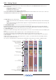
SD5 - Getting Started 1.9 Channel Processing 1.9.1 Dynamic EQ ........................................................................... The EQ section comprises four user-configurable parametric filters with Dynamic Control for up to 24 Channels and a pair of swept High-pass and Low-pass filters. The EQ is accessed by touching the on screen display to Assign the channel (the colour changes to yellow) and then using the controls on the right hand side of the input module.
SD5 - Getting Started 1.9.2 Dynamics .............................................................................. The dynamics are accessed by touching the words Comp or Gate just below the EQ graph on screen to open the dynamics panel. There are two dynamics modules, the first of which can function as a simple compressor, a 3 way multiband compressor, or a de-esser, according to the comp/multi/desser button to its left.
SD5 - Getting Started 1.9.3 Auxiliaries ............................................................................. The auxiliaries can be accessed by pressing the Quick Select Aux button and touching the auxiliary row on screen or using the Screen Scroll buttons on the left of the worksurface Using either of these methods, the highlighted auxiliaries on the input screen will change.
SD5 - Getting Started 1.10 The Matrix To open the Matrix Inputs panel, touch the Matrix button on the Master Screen. The window that opens allow you to route inputs to the Matrix Output Channels, and set the Matrix crosspoint levels. To route an input, touch the top of the appropriate Matrix column. This opens a standard SD5 input routing page.
SD5 - Getting Started 1.11 Control Groups Any number of input channels and output channels can be connected to one or more of the 24 possible Control Groups. They can then all be operated from a single worksurface control. Changes to the Control Group fader, mute or solo or controls will affect all channels connected to the group.
SD5 - Getting Started 1.12 Multi-channel formats If you are working in Surround, or using another multi-channel format, you can create LCR, LCRS and 5.1 busses in the Session Structure panel described earlier in this chapter Multi-channel inputs are controlled by routing each component through a mono channel and then linking those channels via a 'Multi' channel. To start with, use the normal input and output routing procedures to route each component through a channel.
SD5 - Getting Started 1.13 Solo Setup The SD5 Solo panel is accessed from a button at the top of the Master Screen. Some of the controls on this panel are duplicated on the worksurface, immediately above the Master Screen. There are two solo busses and each solo button on the console can be independently assigned to use Solo1, Solo2 or Solo 1+2. Therefore, if the console was being used for Stage monitors, the first solo buss could feed “In-Ear” monitors, and the second solo buss could feed a wedge.