Controller Software User Guide V1.30 This Guide refers to 4REA4 Controller software V1.30+ Please read this guide in conjunction with the 4REA4 Getting Started Guide for details of 4REA4 hardware setup and connections. Before starting please check www.digico.biz for the latest 4REA4 firmware, software and documentation.
1. IMPORTANT - Read before starting 1.1 System operating firmware The function of 4REA4 is determined by the operating software that runs it. Software is updated regularly as new features are added and improvements made. Before attempting to use the APAD App, visit www.digico.biz Support Downloads section to download the latest available version of 4REA4 firmware and Controller software. 4REA4 Firmware is updated using the 4REA4 Controller application.
1.2 Software licence agreement By using 4REA4 you agree to be bound by the terms of the relevant End User Licence Agreement (EULA), a copy of which can be found at http://www.digico.biz/docs/about/legal.shtml. You agree to be bound by the terms of the EULA by installing, copying, or using the software. 1.3 Further information Please refer to the DiGiCo website for further information, knowledgebase and technical support.
Engine Configuration - Input Channels & Busses • The 4REA4 A-Core Engine offers 128 Input channels and 48 configurable busses plus 4 Stereo Area Output busses and 4 Stereo Solo busses. The configurable busses can be used as Groups, Auxes, FX Sends and Matrices. All of these buss types can be Mono or Stereo and a Stereo buss counts as 2 busses from the 48 buss total. Mono busses can only be added or removed in pairs The audio engine runs at 96KHz and doesn’t have an option for any other sample rate.
ALSO NOTE: In Release V1.31 the following DMI cards are not supported • • DMI AMM DMI ME & DMI 3232 1.5 Important Notes for System Administrators User Logins When the 4REA4 Controller application is connected to the 4REA4 itself, a user can log into it as an Administrator with a pre-defined password and be allowed to control any/all of its functions.
Permissions If an Area user has logged in to the 4REA4 Controller software they should, as previously described, only see the channels that are relevant to their Area but they will also see all of the other options and functionality available across the entire engine eg I/O routing, FX parameters, session saving and loading etc. Using the Permissions system, any user can be prevented from accessing these functions and it will normally be advisable that they should be.
2. Contents 1. IMPORTANT - Read before starting ................................................................................................. 2 1.1 System operating firmware 2 1.2 Software licence agreement 3 1.3 Further information 3 1.4 Overview 3 1.5 Important Notes for System Administrators 5 2. Contents ............................................................................................................................................. 7 2.1 User Interface 9 2.
9.6 Config / Area Manager (V1.10+) 46 9.7 Audio / I/O Settings 47 9.8 Audio / Audio Sync 47 9.9 Audio / Source Selector 48 9.10 Audio / Audio Playback 49 9.11 Audio / AMM 50 9.12 Talkback 52 9.13 Mute Groups 53 9.14 SigGen 54 9.15 Controllers 55 9.16 Remote Control / Quick Setup 56 9.17 Remote Control / Advanced 57 9.18 Remote Control / Simulator 58 Engine / Control 58 9.19 10. Control Setup ...........................................................................
15.10 DMI ADC 86 15.11 DMI DAC 87 15.12 DMI Aviom 87 15.13 DMI Cards - Updating Firmware and FPGA Codes (V1.20+) 87 SD-Rack Cards 88 15.14 Appendix E – Multiple Software Controllers ................................................................................. 89 16. 17. 16.1 Sessions 89 16.2 Snapshots 89 16.3 Areas 89 Processing specs ......................................................................................................................... 90 2.
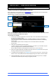
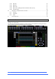
2.2 Processing View 2 1 3 6 4 5 4REA4 Controller Software User Guide 10 V1.
1 Selected channel – Displays the name, type and number of the currently selected channel. Click to edit channel name. A name can have up to 8 characters, however only the first 6 characters will be displayed in the fader strip display. To store a name for instant access later on, click a ‘quick name’ box and click Store. 2 Active Mix – Displays the name, colour, type and number of the currently active Mix. If a CG Spill is active, the Mix name is surrounded by a red square.
The following displays are available in this version of software: Gate and Comp Gate with signal meter, graph, gain reduction meter, Threshold and Depth control; Compressor with signal meter (pre and post), graph, gain reduction meter, Ratio, Threshold and Gain control. Gate Comp Signal meter, graph, gain reduction meter, sidechain graph, histogram, Threshold, Depth, Hold, Attack and Release control.
Preset – Click to access the Presets library window for the current page. Presets let you store and recall settings for individual processing blocks such as EQ and Compressor and also for the whole Input or Mix channel. Input and Mix channel processing presets are accessed from their Overview page. The Presets window shows 3 types of Preset: Factory, User (stored in the 4REA4) and USB (stored in the USB key). Click to select a preset and use the buttons to Recall, Overwrite or Delete.
2 1 CGs – Displays name, members (assigned channels) and whether the ‘Fader to Zero dB’ option is enabled. Use the Bussing screen to assign channels. Mix channels – Displays name, Ext Input, meter (pre-processing), polarity, EQ graph, compressor graph, and channel meter (post-processing). 1 Scroll the list up or down if the members are too many to fit in the strip. 2 Pull down the name of a selected Mix channel to display details of the Ext Input source such as socket number.
Input channels 1 Input – Displays the Input source, Gain and Digital Trim. Icons show 48V phantom power and polarity setting. 2 Processing – Thumbnail graphs of Filters, EQ, Gate and Compressor complete with sidechain. EQ and filter curves display dim when switched Out. Dynamics display grey when switched Out. 3 Insert – Assignment and bypass status are shown for the two Insert points. 4 Delay – Shows the setting for the selected channel.
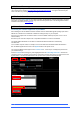
2.6 Input Setup The Input Setup page provides access to the Input Channel source patching and other Input settings. 1 3 4 2 1 Source Select – Open the drop-down menu to choose which source to patch to the channel, click the Socket box then drag the mouse over the value to select the required socket or number, then click Apply.
2.7 Ext In You can assign an external input to any Mix channel, for example for bus summing, combining console outputs, or external communications. The Ext Input sums with the Mix channel pre-insert and is affected by the Mix processing and fader. Open the Source Select drop-down menu to choose which source to patch, click the Socket box then hold and drag the mouse to select the required socket or channel number, then click Apply.
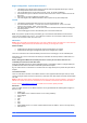
2.9 Gate (Ducker) This page provides access to the Input channel Gate settings and sidechain filter. Press the Presets button to access the Gate presets. This includes the option of a channel Ducker to replace the Gate. 3 1 2 1 Key Input – Click the Key Input Source box to open a window for selecting the Key (trigger) input to the Gate. An adjustable HPF and LPF filter can be switched in to limit the frequency range of the Key signal. 2 Histogram – Shows Gate activity over time.
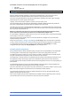
2.10 Inserts You can insert external equipment, external plugins, or one of 16 internal Rack FX units into a channel. Input channels provide two Insert points (post Gate and post EQ/Comp). 1 2 1 Insert Settings – Click In to switch the inserted device in circuit. Click Unassign to clear the current Insert assignment. 1 Insert Patch – Use the drop-down menus to assign the Send and Return to physical sockets, I/O Ports or FX units. Click and drag the boxes to select socket or number.
2.11 EQ The Parametric Equaliser provides 4 fully adjustable bands of equalisation. It can be adjusted using the mouse on the graph by clicking and dragging the parameter values. ⚙ Click Setup and then click the navigation tabs area to access channel options including the processing order of EQ and Compressor. The default order is EQ first, Compressor next. You can invert the order on a per channel basis or globally. The EQ/Comp order for each channel is stored in Session files.
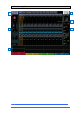
2.12 GEQ A 28-band 1/3 octave Graphic Equaliser is provided on each of the Mix outputs. It can be adjusted using the mouse. 1 2 3 1 Graph – The top part of the screen shows the combined frequency response curve of the GEQ. The curve turns green when the GEQ is switched in and grey when switched out. An RTA of the SOLO signal with optional peak band indication is also superimposed on the graph.
2.13 Compressor This page provides access to the channel Compressor settings and sidechain filter. ⚙ Click Setup and then click the navigation tabs area to access channel options including the processing order of EQ and Compressor. The default order is EQ first, Compressor next. You can invert the order on a per channel basis or globally. The EQ/Comp order for each channel is stored in Session files. It is not stored in Snapshots.
2.14 Delay The delay settings for all the channels or mixes are shown on this page, with the currently selected channel highlighted. Use the mouse to change its value or click and drag on another parameter box to adjust the delay for a different channel. Click the In buttons to toggle the delay in or out. Input delays can be adjusted up to 340ms, Mix delays up to 680ms. ⚙ Click Setup and then click anywhere in the Delay page to access the unit and temperature preferences for the Delay.
3. Main screen 3.1 Main User Interface Note that the Mix selection buttons on each channel determine the functionality of the channel faders and the channel strip On/Off buttons. By default, the Mix button is selected for the current Area’s Area Out Buss and this means that all other relevant channels types’ fader and on/off buttons will be assigned to mix to that Area Out. For example, to send an input channel to the Area Out, ensure that the Mix button is pressed (red highlight) for the Area Out channel.
1 Main & System Buttons – Toggles UI view between the main view shown above and the system view which provides settings related to the system, such a USB drive location and 4REA4 connections 2 Bank Navigation – Displays banks 1, 2 and 3, each bank can be selected to bring it to the main bank view. 3 Main Bank View – Displays a single enlarged bank for easy access to faders and various functions, layer selection buttons can be found in the bottom right.
3.2 Home When no screen mode is selected, the System screen displays a Home page with a System Status dashboard, real time clock and access to User login. Press the Home key to come back to this page and present a familiar state of the display controls. Pressing this key will exit from any screen mode or menu, unselect the currently selected channel, make the current area the active Mix, and Layer A active across all fader banks. 1 3 2 4 1 System Status – Displays a list of system components.
3.3 User login The system Administrator can set up to 9 User Profiles to protect settings and restrict access to certain functions. Click Switch User on the Home page to log in as a different User. 1 2 1 Users list - Shows available Users. These can be configured and enabled in the Engine / Config / User Profiles screen. The Admin User is always displayed. Icons indicate if the User has a password or User Snapshot set. Click a User to select then click Login to change User.
4. Meters Different tabs give access to meters for all Input channels, all FX Sends and Returns, all Mixes, and up to 4 configurable User views, as well as a Real Time Analyser. Meters tabs – Channel name is shown below each meter. A gain reduction meter and gate active indicator are also displayed, these show activity in red when switched In, and in grey when switched out. The meter source point can be globally set for all Inputs and all Mixes independently.
5. FX The FX screen gives access to the 16 virtual FX slots. 3 1 4 5 2 5 1 FX bar – The 16 slots are shown across the top of the screen either empty or with FX devices loaded. The FX name, current Library preset and metering is shown next to each icon. Click and drag left to right to view all the FX slots. Click a device or empty slot to select. 2 Presets – Click the Presets button to access the FX Presets. The Presets are grouped by FX type.
1 2 1 Back Panel – Use this view to edit the routing for the selected FX. Use the drop-down box to choose between Unassigned, Insert or Buss->Return. 2 Buss->Return patches the FX device as a system effect with a Send bus and a dedicated stereo FX Return channel. Select the bus you want the FX to use and click Apply to confirm. The source patch defaults to the corresponding FX Send bus if available in the current bus configuration. The output patch defaults to the dedicated stereo FX Return channel.
6. Routing Use this screen to patch inputs and outputs from / to analogue sockets, I/O Ports, A3232 ports, DMI Cards. The patch is presented as a matrix view with red boxes indicating an active connection. Crossed out red boxes indicate an invalid connection, for example when the output is not available in the current system configuration.
6.2 Outputs Patch Mixes, Direct Outs, FX or Solo (displayed on the left) to outputs (displayed on top). 2 1 1 Sources – Channel names are displayed. Click a channel name or number to edit its name. 2 Destinations – The output number is greyed out if already in use, or striped when the output is not available in the current system configuration. Click a socket number to open a window with a list of current assignments and available controls for the socket.
7. Bussing The Bussing screen lets you view and adjust sends, routing and assignments for the currently selected channel. It offers an alternative to using the fader strips, Mix keys and Assign / Pre keys. 2 3 1 4 5 Input channels – Displays routing, assignments and Direct Out controls. 1 Aux sends are shown as a purple bar if post-fade, or as a red bar if pre-fade. The bar is filled in if the channel is assigned to the Mix, the outline only is shown otherwise.
2 1 3 Aux and FX sends – Displays routing and assignments of Input channels, FX Returns and Groups to the selected Mix. 1 Sends overview – Sends from Inputs, FX Returns and Groups are shown as a purple bar if postfade, as a red bar if pre-fade. The bar is filled in if the channel is assigned to the Mix, the outline only is shown otherwise. Use the tabs on top to display Inputs, FX Returns or Groups.
CG and Groups – Displays channel assignments to the CG or Group. Click On/Off to toggle the channel assignment to the CG or Group. For CGs, use the tabs on top to display different channel types. ⚙ Click Setup and click anywhere in the Routing screen to access the CG fader to 0dB option. This forces the CG level at 0dB. 4REA4 Controller Software User Guide 35 V1.
8. Snapshots Use this screen to manage snapshots. Up to 800 snapshots may be stored, and one or more Cue Lists can be created from the snapshots. Global Safes and per snapshot Recall Scopes can be set to block certain parameters from recall. 8.1 Snapshot Manager Gives access to the snapshot list for editing or recalling. 2 1 3 4 5 1 Snapshot list – Choose to display the list of all 800 snapshots or the Current Cue List.
Click the Lock button to lock the snapshot from any edit thus preventing accidental changes. Click Copy Scope To… to copy the current recall scope settings to either a single snapshot, a range of snapshots or all snapshots. You can automate the recall of one or more other snapshots when you recall a snapshot. Touch Duration to open the Duration settings for the snapshot (see below). 6 Click Copy to copy the content and Recall Scope of the currently selected (blue) snapshot.
8.3 Duration Recall You can automate the recall of one or more other snapshots when you recall a snapshot. A delay time can be set for each automatically recalled snapshot within the host snapshot. Set the Snapshot Number to select the Snapshot you wish to recall. Its name is displayed below the box. Set the Delay time for the snapshot recall. This is the time the system waits before recalling the Snapshot after you have recalled the host Snapshot. Time can be set from 0 sec (instant) to 4 minutes.
Use the tabs on the left to view the different parameter groups. Scroll to zoom in and out of the matrix view. Click and drag to navigate through the matrix. Click an item to toggle. Items highlighted in green will be updated, all other items will be ignored. Click the + and – symbols to show and hide nested parameters. Click a parameter label on top of the table to toggle one parameter for all channels. Click a channel label on the left to toggle all parameters for one channel.
8.5 Cue List Editor A Cue List is a custom list of snapshots selected from the list of available snapshots. Cue Lists can be named, saved, recalled and deleted. 2 1 1 Current Cue List – Drag and drop snapshots here to create a Cue List. Snapshots can be placed in any order and repeated any number of times in the list. To remove a snapshot from the Cue List, click the trash can icon to the right of the snapshot name. 2 Click Save to name and store the current Cue List.
8.7 Global Snapshot Safes Snapshot Safes prevent certain channels or parameters being overwritten by a snapshot recall. Contrary to the Recall Scope, this setting is global, affecting ANY snapshot recall. It is typical for certain settings such as macro assignments to be made safe so their settings are global within the session. 6 5 1 4 2 3 Scroll to zoom in and out of the matrix view. Drag up/down or left/right to navigate through the table. Click an item to toggle its state.
8.8 Area Safes The snapshot list is divided into four sections, each section is associated with a single area and has a total of 200 snapshots. Snapshots 1 – 200 are associated with Area 1, snapshots 201 – 400 with Area 2, snapshots 401 – 600 with Area 3 and snapshots 601 – 800 with Area 4. An Area Safe prevents certain channels or parameters being overwritten by any snapshot recall which is not associated with the selected area.
9. Engine Setup These pages give access to the bus configuration, Input stereo configuration, network settings, audio settings and User Profiles. 9.1 Config / Structure Use this page to reconfigure the architecture of the 48 Mix busses available. 2 1 1 Bus configuration – Click and drag a box to set the number of mono / stereo Groups, FX sends, Aux sends and Matrix outputs. You can choose any combination but note that mono busses can only be added / removed in pairs.
9.3 Config / Name Use this page to change the name of a single channel or reset the name of a range of channels. Name of individual channels can be edited from the Processing Screen. 1 2 1 Channel Selection - Set the channel Type from the drop-down menu. Click Select All or set the Start and End to select a range of channels. 2 Name – Press Reset to restore the default channel names to the selected range. Click the name box to edit the name when a single channel is selected. 9.
9.5 Config / User Profiles Up to 10 User Profiles including an Administrator can be set to restrict operator access and protect selected functions. 2 1 1 Users – The Admin user has access to all functions and can set permissions and allocate passwords if required for the other users. The password, if one is set, is required when the User logs in or changes User. Icons in the list indicate if a password is set and if the User is active. Click a User to edit its profile.
Area User provides a recommended typical set of permissions for a single Area user – these can subsequently be edited as required. 9.6 Config / Area Manager (V1.10+) Use this view to define which channels will appear in the strip assign view for each area. In this way, Administrators can pre-define which channels are accessible in which areas.
2 Assigned Area Indicator – When a channel has been made available in an area (or all areas) a number will show which area the channel is assigned to. 3 Assigned to this Area Highlight – To make a channel available in an area, click on the channel in the display and it will be highlighted in orange.
9.9 Audio / Source Selector The Source Select page allows the configuration of up to 20 Source Selectors, each with up to 20 sources, that can be controlled via GPIO or AC Remote Controllers. Sources configured in a Source Selector are mutually exclusive on the output Mix. This can be used for example for selection of background music in a room, with automatic crossfades when switching sources.
9.10 Audio / Audio Playback Audio WAV files can be stored and played by the 4REA4 and used as an input source to any Input channel in mono or stereo. Files must first be uploaded to the 4REA4 from the computer running the Controller software. 1 2 1 With the Controller computer connected to the 4REA4, click on Upload File and select the required audio file from the Controller computer’s drive – then follow the on-screen instructions to upload the file.
9.11 Audio / AMM The Automatic Mic Mixer (AMM) provides automatic level control of multiple microphones for spoken word applications such as conferences and discussion panels involving several participants each with their own mic around a table. This improves intelligibility and can reduce the risk of feedback by reducing the levels of mics which are not being spoken into. Once set, the AMM needs little or no change at all whilst still allowing the engineer to maintain absolute control of the mix.
Input Assign 1 3 2 The Input Assign window is used to specify the number of AMMs and the members of each AMM. 1 Inputs – Drag and drop inputs from this area into the desired AMM. All 128 inputs can be accessed, in blocks of 32, via the tabs above the input strips. Turn on Block Select and touch the first and last item you wish to assign to drag a range of channels into the lower window. 2 AMM(s) – Here you can view the members of each active AMM.
9.12 Talkback Use this screen to assign and configure Talkback. Assign – Click a Mix button to assign Talkback. 2 1 3 4 Settings – Use this page to choose the Talkback source and set its options. 1 General – The default Talk switch operation is momentary (press and hold while talking). Turn on Enable Latching for latching operation (press to turn on, press again to turn off).
9.13 Mute Groups 4REA4 provides 8 Mute Groups in addition to the 24 CGs. This page lets you assign channels and mixes to Mute Groups and control Mute masters. You can assign one or more macros to control the Mute Groups using the Engine / Control / Macros menu. 1 4 2 3 1 2 3 Select the Mute Group using the tabs at the top of the page. These tabs let you navigate all available Input channels, FX Returns and Mixes. Click the on/off buttons to toggle the channel assignments to the Mute Group.
9.14 SigGen The Signal Generator provides a test signal to help you align and test components of a sound system. Assign – Click a Mix button to assign the SigGen. The signal routes through the Mix processing, therefore will be affected by the Mix EQ and compressor. The SigGen is disabled while Talkback is active. Settings – The SigGen Level can be set from fully off to full scale +18dB. Click the Mute button to turn off. There are 4 types of signal available: Sine - A pure tone.
9.15 Controllers Up to 8 GPIO modules and 16 A-Control remote controllers per device type are configurable, each with its own assignments and functions. Refer to the AC Remote Controller Getting Started Guides for information on the device hardware and connection.
9.16 Remote Control / Quick Setup Quick Setup lets you quickly assign one or multiple channels to the AC controller strips, automatically mapping the keys and faders / rotaries to a set of default functions and parameters. 1 3 2 ⚙ Before you start, click Setup and click anywhere in this screen to edit the default settings for Quick Setup. These settings determine the function of the strips at the moment of assigning to the AC device. They don’t affect strips which are already assigned.
9.17 Remote Control / Advanced Advanced allows one-by-one assignment of buttons and faders / rotaries. 1 3 2 1 Click a strip header to expand the view and display the assigned functions or parameters for the strip. 2 Click a control to assign a function or parameter. Note that the screen will display two rows of rotary controls for the AC6. The lower row is the main function, the upper row is the secondary (push ‘n turn) function. 3 Select the Layer you want to edit.
9.18 Remote Control / Simulator Use this screen to simulate the operation of the selected device. Click a button on the screen to control the assigned function. Click and drag a fader / rotary control to control the assigned parameter. 9.19 Engine / Control The Engine/Control tab allows access to the setup of the 8 x 4REA4 front panel Macro keys and the onboard Engine GPIO ports.
The brightness of the front panel Macro buttons and Switches can be controlled in Engine/Control/Macros/Display. The onboard Engine GPIO ports are configured in Engine/Control/GPIO/Advanced. Click on one of the 8 x on-screen GPIO IN or OUT buttons to open a display where a function can be selected from a drop-down list. Use the Simulator screen to simulate the operation of the device. 4REA4 Controller Software User Guide 59 V1.
10. Control Setup These pages let you configure the strip layout, macros, control preferences, CG Spills, audio settings and Controllers’ Settings. 10.1 Control / Strip Assign Any combination of Input channels, FX, Group, Aux, Area Outs and CG strips can be assigned to the 6 layers of faders. This lets you customise the controller layout to suit the application. The layout is stored within snapshots and can be made Safe from snapshot recall.
10.2 MIDI Control (V1.10+) 4REA4 can be controlled via a TCP/IP MIDI connection TCP/IP control is available via any Network port on the 4REA4. Messages are sent using the MIDI format, as described in 4REA4 MIDI TCP IP Protocol V1.0#5.pdf and in 4REA4 MIDI table V1.0.pdf (these documents are available at: https://www.digico.biz/docs/about/manuals_1.shtml ) The 4REA4 uses a range of MIDI channel numbers within the TCP/IP messages.
from the 4REA4 Controller to the corresponding DAW controls. If the Bank Up / Down function is assigned to the 4REA4’s Macro Buttons, fader bank navigation will also be enabled in the DAW. 4REA4 Controller Fader strips can be assigned as MIDI Strips. There are 32 MIDI Strips available. Each can be assigned to transmit a custom MIDI message. This is ideal for controlling audio within a Digital Audio Workstation (DAW), a slave mixer, or parameters on external equipment such as effects devices.
10.3 Control / Macros 4REA4 Controller provides up to 26 assignable keys on the right of the application. 1 2 1 Open the Function drop-down menu and select the function to assign. Set the Channel Type and Channel Number to select the required channel (only applies to certain functions). Turn on Invert LED if you want the macro LED to be lit when the function is off. Press Apply to confirm the changes. Macro assignments are stored within snapshots.
10.4 Control / Control Preferences 2 1 3 1 Custom Rotary Functions– Use the drop-down menus to select the required Function for each Custom strip rotary control. Available functions are Unused, Direct Out, Send Level (Aux or FX sends), HPF Frequency, Compressor Threshold, and Channel Level. Click Apply to confirm the change. 2 Display Parameter Values on LCD will display the fader position in dB value or value of the rotary function every time the fader or rotary are moved.
10.6 Audio / Solo Set your preferences for the solo monitoring system. The strip solo key operates in the following way: • • Input solo overrides mix solo Releasing input solo restores previous mix solo 1 3 2 4 1 Solo Number – Set the solo bus that the 4REA4 will use for the monitoring system. This affects the function of the solo keys, Listen key, and audio to the 4REA4 headphones.
10.7 Audio / Audio Playback Set up and manage stereo playback to a USB key. 4REA4 can play mono or stereo WAV files, 16bit or 24bit, with sample rate of 44.1, 48 or 96kHz. USB recording is fixed stereo WAV 24bit 96kHz (approximately 34MB per minute or 2GB per hour). The USB key must be formatted FAT32 with 32k cluster size. We recommend you format the key using this page prior to use. 3 1 4 2 1 Lists the uploaded and available audio files ready for playback.
10.9 Audio / Metering Ballistics The response of 4REA4 meters on screen can be adjusted to suit the engineer’s preference. To set the global meter source point for Input channels and Busses, click Setup and click the main screen area in the Meters / Inputs screen. 1 2 3 4 1 Use fast Attack and Release for fast response, digital absolute peak meters.
10.10 Config / Network Use this page to configure the IP Address and Unit Name to identify the 4REA4 on the network. 2 1 3 1 IP Settings – To set a static IP Address, click the IP Address box and type in the address. Make sure the Subnet Mask and Gateway are valid, and all devices on the network including Wi-Fi routers, access points or laptops have unique but compatible addresses. The default 4REA4 IP Address is 192.168.1.70 with Subnet Mask 255.255.255.0 and Gateway 192.168.1.254.
11. Utility 11.1 Memory / Session Manager A session file stores the complete 4REA4 setup. This includes the session structure, system preferences, all snapshots and all presets. User Profiles are not stored in session files. Sessions are stored in the 4REA4 and can be transferred between 4REA4 systems or archived via USB key. See Appendix B in this guide for details on Scene and Session memory content. Sessions can be overwritten, renamed or deleted.
11.2 Memory / Preset Manager Use this page to edit and transfer presets. Presets include Channel Processing, Mix Processing, EQ, GEQ, Gate, Compressor, FX parameters. 2 1 1 4REA4 Presets – Lists presets stored in the current session. click a preset to select it. You can Rename and Delete existing presets. click Copy to USB to copy the preset to the USB drive. 2 USB Libraries – Lists presets stored in the USB drive. The files are stored in the USB DiGiCo4REA4/Presets folder.
11.4 Utility / Date/Time Use this page to set the current date and time. The time is displayed in the Home screen and used in the History and Event Logs. 11.5 Control / MIDI (V1.10+) Use this page to assign the MIDI channel number and operate the MIDI Transport controls (MTC). These send out the related MTC messages over TCP/IP. 4REA4 Controller Software User Guide 71 V1.
12. Appendix A – Rack FX The Rack FX selection combines the pristine quality and wide choice offered by boutique plug-ins with the convenience and low latency of onboard processing. 12.1 Rack FX models SMR Reverb - SMR Live is a Spatial Modelling Reverberator featuring 4 fully configurable complex spatial models Classic, Hall, Room and EMT. Each of these models use different reflection and decay algorithms to provide natural sound spaces ideal for Live sound. Classic Emulates high quality plates.
Stereo Tap Delay - Provides a clean digital delay with a maximum delay time of 2.7 seconds. One of the key features of the stereo tap delay is the ability to synchronise the delay times to note intervals based on the effects beats per minute value. The delay has two modes of operation: BPM mode -Delay time is determined by the selected beats per minute and corresponding note value. Standard, dotted and triplet intervals are selectable via the interval selection wheel from whole to 16th intervals.
Chorus - Chorus derives from the late 80’s where different stereo field creation techniques influenced the sound of each chorusing unit. Chorus recreates the classics using 3 stereo-field emulations. These emulations can be switched in any combination creating many different stereo fields. All switches up gives no stereo enhancement. The traditional Rate and Depth controls cover the centre panel. The LFO driving the modulator can be switched to sine or rectified shape.
Attack - Time period for gate to open. Hold - Time period that the gate remains fully open. Release - Time period for gate closing. Maximum gate open time (attack + hold + release) = 500ms. Models: Classic nonlinear - Emulates the faithful 80’s classic gated reverb. Panner - Rapid panning between L and R in the reverb. Short time movement FX. Powerbox - Max power in gated energy. Not as de-correlated as classic non-linear.
VS1 Vocal Shift - VocalShift VS1 is a stereo vocal pitch shifter squeezing two channels of high quality pitch shifting into a single effect. It has a very low latency (<6ms), covers the whole vocal frequency range, and minimises the phasing and flutter artefacts common with many pitch shifters. VocalShift allows large shifts of up to +/- 1 octave, with a further switchable octave downshift. The wide range makes it ideal for theatrical or more extreme musical effects.
Frequency - Adjusts the lower boundary of the region thought to contain sibilance. This will typically be around the 6kHz range. Adjust the value to capture the “ess” heard on the channel. The frequency is adjustable from 3kHz to 8kHz. Like many advanced De-Essers this is not a simple notch filter. Typically you need to set the frequency slightly lower than the centre frequency of the ‘ess’. Reduction - Provides control over the amount of gain reduction applied to the selected frequency band.
• Peak Manual • RMS Manual • Auto Punch • Auto Opto • Slow AutoF • Fast AutoF Knee - Hard or Soft (easy knee model). Link and Relative modes: There are three operating modes with two buttons at the top right of the screen: • • • Normal - Link and Rel buttons turned off. Independent control of each band. Link - All band parameters linked for quick setup. Relative - All band parameters linked for changes relative to settings made before the Rel button was turned on.
13. Appendix B – Snapshot & Session content 13.
13.
14. Appendix C – Template Sessions Template Sessions provide a quick starting point by giving you a simple and familiar layout. They may contain default Snapshots to reset some of the 4REA4 settings such as strip assign layout to a known starting point. They also have default Snapshot Global and Area Safe settings that will serve as a logical starting point for configurations – these settings can be changed and the sessions resaved as User sessions.
15. Appendix D – I/O Module Options Note that DMI Cards and SD Rack (Local) cards must not be “hot swapped” – to insert or remove cards, please power down the 4REA4 Unit first. 15.1 4REA4 I/O Control Via DiGiCo SD Console A DiGiCo SD console can control the I/O connected to a 4REA4 via either a DMI-MADI (B or C) or a DMIOpto. Sockets of I/O either on or connected to the 4REA4 can be tie lined to the connection to the SD console on a per socket basis.
15.2 A164 Wall LCD 1 2 1 Redundancy - A3232 devices can be run in redundant mode 2 Display Settings – The Brightness and Contrast of the displays of each A164 Wall LCD can be controlled by adjusting the controls relative to the correct Port and Device. Note that this menu can also be found under the AStar tab for devices connected via an AStar. 15.
15.4 DMI MADI (B or C) 1 2 3 1 MADI Sample Rate Display – Shows the sample rate of the MADI card 2 96kHz Mode – There are 2 MADI standards when running at 96 kHz, SMUX (48k frame) and High Speed (true or 96k frame). 96Khz SMUX MADI uses a native 48 kHz clock which the DMI can detects and report. This 48kHz SMUX clock cannot be differentiated from a standard 48 kHz without intervention. If SMUX Mode is required, the SMUX mode needs to be manually set.
3 Channel Count – when connecting to an SD console, channels must be ‘reserved’ on the Optocore loop. Choose the number of channels needed from the drop down menus. NOTE: Input Channel Count refers to the inputs from the 4REA4 to the Optocore loop (outputs from the 4REA4) and vice versa for the Output Channel Count 15.6 DMI Dante DMI Dante card will need Dante Network configuration in addition to its Sync Source settings.
15.8 DMI Waves DMI Waves Card will need Soundgrid Network configuration in addition to its Sync Source settings. This is done using either Waves MultiRack or SoundGrid Studio, both of which are available from: http://www.waves.com/downloads 15.9 DMI Mic 8 analogue Mic Pre-Amps with gain and +48V control 15.10 DMI ADC 16 Line level only analogue inputs on 2 x 25 way D-Sub connectors – there is no gain or +48V control on these cards. 4REA4 Controller Software User Guide 86 V1.
15.11 DMI DAC 16 Line level only analogue outputs on 2 x 25 way D-Sub connectors 15.12 DMI Aviom 16 Output channels at 48KHz (with SRC) supporting the Aviom A-Net Pro16 protocol 15.13 DMI Cards - Updating Firmware and FPGA Codes (V1.20+) DMI Cards require both Firmware and FPGA Code. Connect Controller to a 4REA4 containing one or more DMI cards.
If a DMI Card is fitted in a slot then it will show the Current versions of Firmware and FPGA Code running on the card and any Available versions. Firmware Version 0 indicates no valid firmware for that DMI Card type. FPGA Code versions are denoted by dates and a blank entry denotes no valid FPGA code for that DMI Card type. An Available version will be shown if a file suitable for the DMI Card type is found in the following location on the machine running Controller: Windows: C:\Program Files (x86)\DiGiCo\
16. Appendix E – Multiple Software Controllers 16.1 Sessions In a typical Multi-Controller system, each Controller computer would store and recall its own Session independently of other Computers running Controller software. Although the 4REA4 Engine data would be the same in each Controller’s Session file, the Controller data would be unique to the Controller that stored the Session. When loading Multi-Software Controller sessions, the last user to store the Session would recall the Session as normal.
17.
Band 3 Bell Band 4 Selectable HF Shelving, Bell, Lo-Pass FX Bell Width Non-constant Q, variable, 1.