
User`s guide

9XTend™ RS-232/422/485 RF Modem User’s Guide
8
2. Interfacing Protocol
The 9XTend RS-232/422/485 RF Modem supports the following interfacing protocols:
• RS-232
• RS-485 (2-wire) Half-duplex
• RS-485 (4-wire) and RS-422
2.1. RS-232 Operation
2.1.1. DIP Switch Settings and Pin Signals
* The ‘Pin Reference Name’ provides an associative tag that references commands used to define pin behaviors.
GPI stands for "General Purpose Input" and GPO stands for "General Purpose Output". As an example, the CD
command is used to define the behavior of GPO2 (DB-9 pin number 1). The ‘Pin Reference Name’ is the name
used when referring to XTend commands and parameters.
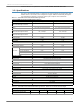
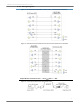
Table 2-01. RS-232 Signals and their implementations on the XTend RF Modem
(Low-asserted signals are distinguished by horizontal line over pin name.)
DB-9 Pin
RS-232
Name
Pin Reference
Name*
Description Implementation
1 DCD GPO2 Data-Carrier-Detect Connected to DSR (pin6)
2 RXD DO Received Data Serial data exiting the RF modem (to host)
3 TXD DI Transmitted Data Serial data entering into the RF modem (from host)
4 DTR GPI2 Data-Terminal-Ready Can enable Power-Down on the RF modemy
5 GND - Ground Signal Ground
6 DSR GPO2 Data-Set-Ready Connected to DCD (pin1)
7
RTS
/
CMD
GPI1
Request-to-Send /
Command Mode
Provides RTS
flow control or enables Command Mode
8 CTS GPO1 Clear-to-Send Provides CTS flow control
9 RI - Ring Indicator
Optional power input that is connected internally to the
positive lead of the front power connector
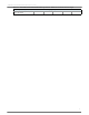
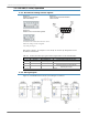
Figure 2-01.
RS-232 DIP Switch Settings
DIP Switch settings are read and applied
only while powering-on.
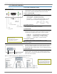
Figure 2-02.
Pins used on the female RS-232 (DB-9)