
User`s guide

9XTend™ RS-232/422/485 RF Modem User’s Guide
7
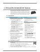
1.3. External Interface
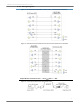
Figure 1-03. DIP Switch Settings of the XTIB-R (RS-232/485) Interface Board
1-01a. Config (Configuration) Switch
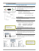
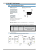
Figure 1-01. Front View
The Config Switch provides an alternate method for entering into
Command Mode. To enter Command Mode at the default RF data rate
of the modem, hold the Config Switch down for two seconds.
1-01b. I/O & Power LEDs
LEDs indicate modem activity as follows:
Yellow (top LED) = Serial Data Out (to host)
Green (middle) = Serial Data In (from host)
Red (bottom) = Power/TX Indicator (Red light is on when
powered; it pulses on/off briefly during RF transmission.)
1-01c. DB-9 Serial Port
Standard female DB-9 (RS-232) connector. This connector can be
also used for RS-485 and RS-422 connections.
1-01d. RSSI LEDs
RSSI LEDs indicate the amount of fade margin present in an active
wireless link. Fade margin is defined as the difference between the
incoming signal strength and the modem's receiver sensitivity.
3 LEDs ON = Very Strong Signal (> 30 dB fade margin)
2 LEDs ON = Strong Signal (> 20 dB fade margin)
1 LED ON = Moderate Signal (> 10 dB fade margin)
0 LED ON = Weak Signal (< 10 dB fade margin)
1-01e. Power Connector
7-28 VDC* power connector (Center positive, 5.5/2.1mm)
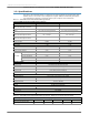
1-02a. DIP Switch
Figure 1-02. Back View During each power-on sequence (reset or boot), the modem is auto-
matically configured according to the positions of the DIP Switch. The
DIP Switch provides integrators with a limited number of external
programming options. [Refer to Figure 1-03 for configuration options]
1-02b. Antenna Port
The antenna port is a 50Ω RF signal connector for connecting to an
external antenna. The connector type is RPSMA (Reverse Polarity
SMA) female. The connector has threads on the outside of a barrel
and a male center conductor.
1-01a.
Config Switch
1-01b.
I/O & Power LEDs
1-01c.
DB-9 Serial Port
1-01d
RSSI LEDs
1-01e.
Power Connector
* Note: The XTend RF modem can accept
voltages as low as 5V.
Contact Digi Technical Support
to implement this option.
1-02a.
DIP Switch
1-02b.
Antenna Conector
Refer to the tables in “Automatic
DIP Switch Configurations” on
page 23 regarding configurations
triggered by the positions of the
DIP Switch (during power-up).