
User`s guide

9XTend™ RS-232/422/485 RF Modem User’s Guide
24
4.2. Programming Examples
Refer to “Command Mode” on page 21 for information regarding entrance into Command Mode,
sending AT commands and exiting Command Mode.
4.2.1. AT Commands
Digi has provided X-CTU software for programming the modem using an extensive list of AT Com-
mands. The X-CTU software provides an interface that is divided into four tabs that facilitate the
following functions:
• PC Settings tab - Setup PC serial port to interface with an RF modem
• Range Test tab - Test RF modem's range in varying environments
• Terminal tab - Configure and read XTend RF modem parameters using AT Commands
• Modem Configuration tab - Configure and read RF modem parameters
To install the X-CTU Software:
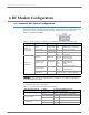
PC Settings Tab (X-CTU Software)
As stated in “Serial Communications” on page 13, in order to communicate data to the RF modem
through the PC, the baud (serial data rate), data bit, parity and stop bit settings on the PC serial
port must match those of the modem. The 'PC Settings' tab provides a software user interface that
facilitates the modification of PC serial port setting.
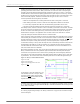
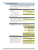
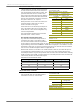
PC Setup
Figure 4-02. Setup for RF Modem Configurations through X-CTU Software
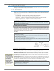
Terminal Tab (X-CTU Software)
A terminal program has been built into the X-CTU software and is located under the 'Terminal' tab.
The Terminal tab provides an easy-to-use interface for programming the modem.
Multiple AT Commands. Multiple AT commands can be entered on one line with one carriage
return at the end of the line. Each command must be delimited by a comma (spaces in between
are optional). The "AT" prefix is only sent before the first command and should not be included
with subsequent commands in a line.
System Response. When a command is sent to the modem, the modem will parse and execute
the command. Upon successful execution of a command, the modem returns an "OK" message. If
execution of a command results in an error, the modem returns an "ERROR" message.
Restore RF Modem Default Parameters (Using the ‘Terminal’ tab of the X-CTU Software)
Double-click the ‘setup_X-CTU.exe’ file that is located on the Digi CD and under the ‘Downloads’
section of the following web page: www.maxstream.net/helpdesk/download.php. Then follow
the prompts of the installation screens.
1. Set the DIP Switch to RS-232 mode. [Switches 1 & 5 are ON (up) and the remaining 4
switches are OFF (down).]
2. Connect the male DB-9 connector of the PC with the female DB-9 connector of the RF
modem using an RS-232 cable.
3. Power the RF modem through the power connector.
4. Go to the PC Settings tab and select parameter values from the drop-down lists that match
the current parameter values of the RF modem.
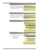
Example: Both of the following examples restore the XTend Modem's factory defaults and save
the parameters to non-volatile memory.
Method 1 (One line per command)
Note: Do not send com-
mands to the modem
during flash program-
ming (when parameters
are being written to the
modem registry).
Wait for the "OK" sys-
tem response that fol-
lows the ATWR
command before enter-
ing the next command
or use flow control.
Note: Do not send com-
mands to the modem
during flash program-
ming (when parameters
are being written to the
modem registry).
Wait for the "OK" sys-
tem response that fol-
lows the ATWR
command before enter-
ing the next command
or use flow control.