
User`s guide

9XTend™ RS-232/422/485 RF Modem User’s Guide
13
3. RF Modem Operation
WARNING: When operating at 1 Watt power output, observe a minimum separation distance of 2' (0.6m) between
modems. Transmitting in close proximity of other modems can damage modem front ends.
3.1. Serial Communications
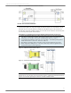
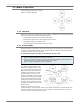
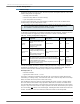
3.1.1. RS-232 and RS-485/422 Data Flow
The XTend RS-232/422/485 RF Modem interfaces to a host device through a standard DB-9 con-
nector. Devices that have a standard DB-9 (RS-232) serial port can connect directly through the
pins of the modem as shown in the figure below.
Figure 3-01. System Data Flow in an RS-232 environment
3.1.2. Host and RF Modem Settings
Serial communications between a host and an XTend RF Modem are dependent upon having
matching baud rate, parity, stop bit & number of data bits settings. Failure to enter the modem
into AT Command Mode is most commonly due to baud rate mismatch. Refer to the table below to
ensure host serial port settings match those of the modem.
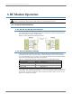
Both the RF modem and host (PC) settings can be viewed and adjusted using Digi's proprietary X-
CTU Software. After connecting an RF modem to a PC via their respective serial connections, use
the "Terminal" or "Modem Configuration" tabs to configure RF modem settings. Use the "PC Set-
tings" tab to configure host settings.
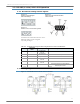
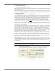
Table 3-01. Parameter Values Critical to serial communications between RF Modem and host
Parameter Setting XTend RF Modem Default Parameter Value
Baud (Serial Data Rate) 9600 bps (BR parameter = 3)
Number of Data Bits 8 (NB parameter = 0)
Parity None (NB parameter = 0)
Number of Stop Bits 1 (NB parameter = 0)