
User`s guide

9XTend™ RS-232/422/485 RF Modem User’s Guide
11
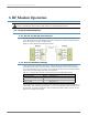
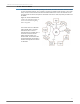
2.3. RS-485 (4-wire) & RS-422 Operation
2.3.1. DIP Switch Settings and Pin Signals
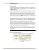
2.3.2. Wiring Diagrams
Figure 2-13. XTend RF Modem in an RS-485 (4-wire) environment
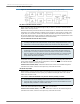
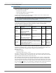
Table 2-03. RS-485/422 (4-wire) Signals and their implementations on the XTend RF Modem
DB-9 Pin
RS-485/422
Name
Description Implementation
2T- (TA)
Transmit Negative
Data Line
Serial data sent from the RF modem
3R- (RA)
Receive Negative
Data Line
Serial data received by the RF modem
5 GND Signal Ground Ground
7 R+ (RB)
Receive Positive
Data Line
Serial data received by the RF modem
8T+ (TB)
Transmit Positive
Data Line
Serial data sent from the RF modem
9PWR Power
Optional power input that is connected internally
to the front power connector
1, 4, 6 not used
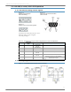
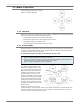
Figure 2-10.
RS-485 (2-wire) Half-duplex
DIP Switch Settings
Figure 2-11.
Pins used on the female RS-232 (DB-9)
Serial Connector
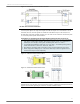
Figure 2-12.
RS-485 (2-wire) w/ Termination (optional)
Termination is the 120 Ω resistor between T+ and T-.
DIP Switch settings are read and applied
only while powering-on.