Digi 9XTend-PKG-R™ RS-232/422/485 RF Modem User’s Guide 90000813_A
9XTend™ RS-232/422/485 RF Modem User’s Guide ©2006-2007 Digi International Digi, Digi International, the Digi logo, and XTend are trademarks or registered trademarks of Digi International, Inc. in the United States and other countries worldwide. All other trademarks are the property of their respective owners. Information in this document is subject to change without notice and does not represent a commitment on the part of Digi International.
9XTend™ RS-232/422/485 RF Modem User’s Guide Contents 1. 9XTend RS-232/422/485 RF Modem 4 5.2.1. Streaming Mode (Default) 51 1.1. Key Features 4 5.2.2. Multi-Transmit Mode 52 1.1.1. Worldwide Acceptance 4 5.2.3. Repeater Mode 53 1.2. Specifications 5 5.2.4. Polling Mode (Basic) 56 1.3. External Interface 7 2. Interfacing Protocol 8 2.1. RS-232 Operation 8 5.3. Acknowledged Communications 57 5.3.1. Acknowledged Mode 57 5.3.2. Polling Mode (Acknowledged) 59 2.1.1.
9XTend™ RS-232/422/485 RF Modem User’s Guide 1. 9XTend RS-232/422/485 RF Modem The 9XTend RF Modem affords OEMs and integrators an easy-to-use RF solution that sustains reliable delivery of data between remote devices. Out-of-box, the modem is configured to immediately sustain long range wireless links between devices. Simply feed serial data into one modem, then the data will surface on the other end of the wireless link. The modem transfers a standard asynchronous serial data stream between devices. 1.
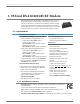
9XTend™ RS-232/422/485 RF Modem User’s Guide 9XTend RF Modems are optimized for use in the US, Canada, Australia and Israel 1.2. Specifications Out-of-box, the 9XTend RF Modem is configured to provide immediate long range wireless links between devices. The modem can be configured to support additional functionality through the use of standard AT and binary commands. Refer to p21 and p23 for more information.. Table 1-01.
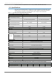
9XTend™ RS-232/422/485 RF Modem User’s Guide Table 1-02. 9XTend-PKG-R RS-232/422/485 RF Modem Specifications - Relative to user-selected TX Power Output Power Requirements (TX currents relative to each TX Power Output option) Typical Transmit Current @115.
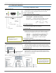
9XTend™ RS-232/422/485 RF Modem User’s Guide 1.3. External Interface 1-01a. Config (Configuration) Switch The Config Switch provides an alternate method for entering into Command Mode. To enter Command Mode at the default RF data rate of the modem, hold the Config Switch down for two seconds. Figure 1-01. Front View 1-01b.
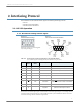
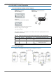
9XTend™ RS-232/422/485 RF Modem User’s Guide 2. Interfacing Protocol The 9XTend RS-232/422/485 RF Modem supports the following interfacing protocols: • RS-232 • RS-485 (2-wire) Half-duplex • RS-485 (4-wire) and RS-422 2.1. RS-232 Operation 2.1.1. DIP Switch Settings and Pin Signals Figure 2-01. RS-232 DIP Switch Settings Figure 2-02. Pins used on the female RS-232 (DB-9) DIP Switch settings are read and applied only while powering-on. Table 2-01.
XTend™ RS-232/422/485 RF Modem User’s Guide 2.1.2. Wiring Diagrams Figure 2-03. RS-232 DTE Device (male DB-9 connector) wired to a DCE RF modem (female DB-9) Figure 2-04. DCE RF modem (female DB-9 connector) wired to an RS-232 DCE Device (male DB-9) Sample Wireless Connection: DTE <--> DCE DCE <--> DCE Figure 2-05.
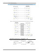
9XTend™ RS-232/422/485 RF Modem User’s Guide 2.2. RS-485 (2-wire) Operation 2.2.1. DIP Switch Settings and Pin Signals Figure 2-06. RS-485 (2-wire) Half-duplex DIP Switch Settings Figure 2-07. Pins used on the female RS-232 (DB-9) Serial Connector Figure 2-08. RS-485 (2-wire) w/ Termination (optional) Termination is the 120 Ω resistor between T+ and T-. DIP Switch settings are read and applied only while powering-on.
9XTend™ RS-232/422/485 RF Modem User’s Guide 2.3. RS-485 (4-wire) & RS-422 Operation 2.3.1. DIP Switch Settings and Pin Signals Figure 2-10. RS-485 (2-wire) Half-duplex DIP Switch Settings Figure 2-11. Pins used on the female RS-232 (DB-9) Serial Connector Figure 2-12. RS-485 (2-wire) w/ Termination (optional) Termination is the 120 Ω resistor between T+ and T-. DIP Switch settings are read and applied only while powering-on. Table 2-03.
9XTend™ RS-232/422/485 RF Modem User’s Guide Figure 2-14. XTend RF Modem in an RS-422 environment RS-485/422 Connection Guidelines The RS-485/422 protocol provides a solution for wired communications that can tolerate high noise and push signals over long cable lengths. RS-485/422 signals can communicate as far as 4000 feet (1200 m). RS-232 signals are suitable for cable distances up to 100 feet (30.5 m). RS-485 offers multi-drop capability in which up to 32 nodes can be connected.
9XTend™ RS-232/422/485 RF Modem User’s Guide 3. RF Modem Operation WARNING: When operating at 1 Watt power output, observe a minimum separation distance of 2' (0.6m) between modems. Transmitting in close proximity of other modems can damage modem front ends. 3.1. Serial Communications 3.1.1. RS-232 and RS-485/422 Data Flow The XTend RS-232/422/485 RF Modem interfaces to a host device through a standard DB-9 connector.
9XTend™ RS-232/422/485 RF Modem User’s Guide 3.1.3. Flow Control Figure 3-02. Internal Data Flow Diagram (The five most commonly-used pin signals shown) DI (Data In) Buffer and Flow Control When serial data enters the modem through the DI pin (Data In), the data is stored in the DI Buffer until it can be processed. When the RB and RO parameter thresholds are satisfied (refer to ‘Transmit Mode’ section for more information), the modem attempts to initialize an RF connection.
9XTend™ RS-232/422/485 RF Modem User’s Guide 3.1.4. Transparent Operation By default, XTend RF Modems operate in Transparent Mode. The modems act as a serial line replacement - all UART data received through the DI pin is queued up for RF transmission. When RF data is received, the data is sent out the DO pin. When the RO (Packetization Timeout) parameter threshold is satisfied, the modem attempts to initialize an RF transmission.
9XTend™ RS-232/422/485 RF Modem User’s Guide 3.2. Modes of Operation XTend RF Modems operate in five modes. Figure 3-03. Modes of Operation 3.2.1. Idle Mode When not receiving or transmitting data, the RF modem is in Idle Mode.
9XTend™ RS-232/422/485 RF Modem User’s Guide Channel initialization is the process of sending an RF initializer that synchronizes receiving modems with the transmitting modem. During channel initialization, incoming serial data accumulates in the DI buffer. RF data, which includes the payload data, follows the RF initializer. The payload includes up to the maximum packet size (PK Command) bytes.
9XTend™ RS-232/422/485 RF Modem User’s Guide 3.2.3. Receive Mode If a modem detects RF data while operating in Idle Mode, the modem transitions to Receive Mode to start receiving RF packets. Once a packet is received, the modem checks the CRC (cyclic redundancy check) to ensure that the data was transmitted without error. If the CRC data bits on the incoming packet are invalid, the packet is discarded. If the CRC is valid, the packet proceeds to the DO Buffer. Figure 3-06.
9XTend™ RS-232/422/485 RF Modem User’s Guide 3.2.4. Sleep Mode Software Sleep Sleep Modes enable the modem to enter states of low-power consumption when not in use. Three software Sleep Modes are supported: • Pin Sleep (Host Controlled) • Serial Port Sleep (Wake on Serial Port activity) • Cyclic Sleep (Wake on RF activity) In order to enter Sleep Mode, one of the following conditions must be met (in addition to the modem having a non-zero SM parameter value): 1.
9XTend™ RS-232/422/485 RF Modem User’s Guide Serial Port Sleep (SM = 2) • Wake on serial port activity • Typical power-down current: < 45 mA Serial Port Sleep is a Sleep Mode in which the modem runs in a low power state until serial data is detected on the DI pin. The period of time the modem sleeps is determined by ST (Time before Sleep) Command. Once a character is received through the DI pin, the modem returns to Idle Mode and is fully operational.
9XTend™ RS-232/422/485 RF Modem User’s Guide 3.2.5. Command Mode To modify or read modem parameters, the modem must first enter into Command Mode (state in which incoming characters are interpreted as commands). Two command types are supported: • AT Commands • Binary Commands For modified parameter values to persist in the modem registry, changes must be saved to nonvolatile memory using the WR (Write) command.
9XTend™ RS-232/422/485 RF Modem User’s Guide Binary Command Mode Sending and receiving parameter values using binary commands is the fastest way to change operating parameters of the modem. Binary commands are used most often to sample signal strength [refer to DB (Received Signal Strength) parameter] and/or error counts; or to change modem addresses and channels for polling systems when a quick response is necessary.
9XTend™ RS-232/422/485 RF Modem User’s Guide 4. RF Modem Configuration 4.1. Automatic DIP Switch Configurations Each time the RF modem is powered-on, AT commands are sent to the on-board module as dictated by the positions of the DIP switches. DIP switch configurations are sent automatically during the power-on sequence and affect modem parameter values as shown in the table below. Figure 4-01. RF Modem DIP Switches Table 4-01.
9XTend™ RS-232/422/485 RF Modem User’s Guide 4.2. Programming Examples Refer to “Command Mode” on page 21 for information regarding entrance into Command Mode, sending AT commands and exiting Command Mode. 4.2.1. AT Commands Digi has provided X-CTU software for programming the modem using an extensive list of AT Commands.
9XTend™ RS-232/422/485 RF Modem User’s Guide Send AT Command +++ ATRE ATWR ATCN System Response OK (Enter into Command Mode) OK (Restore RF modem default parameter values) OK (Write to non-volatile memory) OK (Exit Command Mode) Method 2 (Multiple commands on one line) Send AT Command +++ ATRE, WR ATCN System Response OK (Enter into Command Mode) OK (Execute multiple commands) OK (Exit AT Command Mode) NOTE: Default parameter values o
9XTend™ RS-232/422/485 RF Modem User’s Guide 4.3. Command Reference Table Table 4-03. XTend Commands (The RF modems expect numerical values in hexadecimal. Hexadecimal values are designated by a “0x” prefix. Decimal equivalents are designated by a “d” suffix.
9XTend™ RS-232/422/485 RF Modem User’s Guide Table 4-03. XTend Commands (The RF modems expect numerical values in hexadecimal. Hexadecimal values are designated by a “0x” prefix. Decimal equivalents are designated by a “d” suffix.) AT Binary Command Command AT Command Name Parameter Range Command Category # Bytes Factory Returned Default PE v2.
9XTend™ RS-232/422/485 RF Modem User’s Guide 4.4. Command Descriptions Commands in this section are listed alphabetically. Command categories are designated between the "< >" symbols that follow each command title. By default, XTend RF Modems expect numerical values in hexadecimal since the default value of the CF (Number Base) Parameter is '1'. Hexadecimal values are designated by the "0x" prefix and decimal values by the "d" suffix.
9XTend™ RS-232/422/485 RF Modem User’s Guide BD (Interface Data Rate) Command The BD command is used to set and read the serial interface data rate (baud rate) used between the RF modem and host. This parameter determines the rate at which serial data is sent to the modem from the host. Modified interface data rates do not take effect until the CN (Exit AT Command Mode) command is issued and the system returns the 'OK' response.
9XTend™ RS-232/422/485 RF Modem User’s Guide BT (Guard Time Before) Command The CC command is used to set/read the ASCII character used between guard times of the AT Command Mode Sequence (BT + CC + AT). This sequence enters the modem into AT Command Mode so that data entering the modem (from the host) is recognized as commands instead of payload.
9XTend™ RS-232/422/485 RF Modem User’s Guide CN (Exit AT Command Mode) Command The CN command is used to explicitly exit the modem from AT Command Mode. AT Command: ATCN Binary Command: 0x09 (9 decimal) CS (GPO1 Configuration) Command CS Command is used to select the behavior of the GP01 pin (pin 9). This output can provide RS-232 flow control, control the TX enable signal (for RS-485 or RS-422 operations).
9XTend™ RS-232/422/485 RF Modem User’s Guide DT (Destination Address) Command DT Command is used to set/read the networking address of an RF modem. The modems utilize three filtration layers: Vendor ID Number (ATID), Channel (ATHP), and Destination Address (ATDT). The DT command assigns an address to a modem that enables it to communicate only with other modems having the same address. All modems that share the same DT parameter can communicate with each other.
9XTend™ RS-232/422/485 RF Modem User’s Guide FL (Software Flow Control) Command The FL command is used to configure software flow control. Hardware flow control is implemented with the modem as the GP01 pin (CTS pin of the OEM RF module), which regulates when serial data can be transferred to the modem. FL Command can be used to allow software flow control to also be enabled. The XON character used is 0x11 (17 decimal).
9XTend™ RS-232/422/485 RF Modem User’s Guide HP (Hopping Channel) Command The HP command is used to set/read the RF modem's hopping channel number. A channel is one of three layers of filtration available to the modem. In order for modems to communicate with each other, the modems must have the same channel number since each channel uses a different hopping sequence. Different channels can be used to prevent modems in one network from listening to transmissions of another.
9XTend™ RS-232/422/485 RF Modem User’s Guide KY (AES Encryption Key) Command The KY command is AT Command: ATKY used to set the 256-bit AES (Advanced Encryption Binary Command: 0x3C (60 decimal) Standard) key for encrypting/decrypting data. Parameter Range: Once set, the key cannot be read out of the 0 - (any other 64-digit hex valid key) modem by any means.
9XTend™ RS-232/422/485 RF Modem User’s Guide MK (Address Mask) Command The MK command is used to set/read the Address Mask of a modem. AT Command: ATMK Binary Command: 0x12 (18 decimal) All RF data packets contain the Destination Parameter Range: 0 - 0xFFFF Address of the TX (transmitting) modem.
9XTend™ RS-232/422/485 RF Modem User’s Guide NB (Parity) Command The NB command is used to select/read the parity settings of the RF modem for UART communications.
9XTend™ RS-232/422/485 RF Modem User’s Guide PK (Maximum RF Packet Size) Command The PK command is used to set/ read the maximum size of RF packets transmitted from an RF modem. The maximum packet size can be used along with the RB and RO parameters to implicitly set the channel dwell time.
9XTend™ RS-232/422/485 RF Modem User’s Guide RB (Packetization Threshold) Command The RB command is used to set/read the character threshold value.
9XTend™ RS-232/422/485 RF Modem User’s Guide RN (Delay Slots) Command The RN command is used to set/read the time delay that the transmitting RF modem inserts before attempting to resend a packet. If the transmitting modem fails to receive an acknowledgement after sending a packet, it inserts a random number of delay slots (ranging from 0 to (RN minus 1)) before attempting to resend the packet. Each delay slot is 5 msec (when BR=1) and 54 msec (when BR=0).
9XTend™ RS-232/422/485 RF Modem User’s Guide RP (RSSI PWM Timer) Command RP Command is used to enable a PWM ("Pulse Width Modulation") output on the Config/RSSI pin (pin 11 of the OEM RF Module). The pin is calibrated to show the difference between received signal strength and the sensitivity level of the RF modem. PWM pulses vary from zero to 95 percent. Zero percent means the received RF signal is at or below the published sensitivity level of the modem.
9XTend™ RS-232/422/485 RF Modem User’s Guide RT (GPI1 Configuration) Command The RT command is used to set/read the behavior of the GPI1 pin (GPI1) of the OEM RF Module. The pin can be configured to enable binary programming or RTS flow control.
9XTend™ RS-232/422/485 RF Modem User’s Guide SM (Sleep Mode) Command The SM Command is used to set/read the RF modem's Sleep Mode settings that configure the modem to run in states that require minimal power consumption. AT Command: ATSM Binary Command: 0x01 Parameter Range: 0 - 8 (3 is reserved) Parameter Configuration 0 Disabled 1 Pin Sleep 2 Serial Port Sleep 3 [reserved] 4 Cyclic 1.0 second sleep (RF modem wakes every 1.0 seconds) 5 Cyclic 2.
9XTend™ RS-232/422/485 RF Modem User’s Guide TR (Transmit Error Count) Command The TR command is used to report the number of retransmit failures. This number is incremented each time a packet is not acknowledged within the number of retransmits specified by the RR (Retries) parameter. The number of packets therefore are counted that were not successfully received and subsequently discarded. The TR parameter is not non-volatile and is reset to zero when the RF modem is reset.
9XTend™ RS-232/422/485 RF Modem User’s Guide WA (Active Warning Numbers) Command The WA command reports the warning numbers of all active warnings - one warning number per line. No further information is shown and warning counts are not reset. AT Command: ATWA Parameter Range: Returns string - one warning number per line.
9XTend™ RS-232/422/485 RF Modem User’s Guide 4.5. API Operation By default, XTend RF Modems act as a serial line replacement (Transparent Operation) - all UART data received through the DI pin is queued up for RF transmission. When the modem receives an RF packet, the data is sent out the DO pin with no additional information.
9XTend™ RS-232/422/485 RF Modem User’s Guide Data bytes that need to be escaped: • 0x7E – Frame Delimiter • 0x7D – Escape • 0x11 – XON • 0x13 – XOFF Example - Raw UART Data Frame (before escaping interfering bytes): 0x7E 0x00 0x02 0x23 0x11 0xCB 0x11 needs to be escaped which results in the following frame: 0x7E 0x00 0x02 0x23 0x7D 0x31 0xCB Note: In the above example, the length of the raw data (excluding the checksum) is 0x0002 and the checksum of the non-escaped data (excluding frame delimiter and length
9XTend™ RS-232/422/485 RF Modem User’s Guide TX (Transmit) Request: 16-bit address API Identifier Value: 0x01 A TX Request message will cause the modem to send RF Data as an RF Packet. Figure 4-7.
9XTend™ RS-232/422/485 RF Modem User’s Guide 5. RF Communication Modes The network configurations covered in this chapter are described in terms of the following: • Network Topology (Point-to-Point, Point-to-Multipoint or Peer-to-Peer) • RF Communication Type (Basic or Acknowledged) • RF Mode (Streaming, Multi-Transmit, Repeater, Acknowledged or Polling) The following table provides a summary of the network configurations supported. Table 5-01.
9XTend™ RS-232/422/485 RF Modem User’s Guide 5.1. Addressing Each RF packet contains addressing information that is used to filter incoming RF data. Receiving modules inspect the Hopping Channel (HP parameter), Vendor Identification Number (ID parameter) and Destination Address (DT parameter) contained in each RF packet. Data that does not pass through all three network security layers is discarded. Figure 5-01. Addressing layers contained in the RF packet header 5.1.1.
9XTend™ RS-232/422/485 RF Modem User’s Guide 5.2. Basic Communications Basic Communications are accomplished through two sub-types: • Broadcast - By default, XTend RF Modems communicate through Broadcast communications and within a peer-to-peer network topology. When any modem transmits, all other modems within range will receive the data and pass it directly to their host device.
9XTend™ RS-232/422/485 RF Modem User’s Guide 5.2.2.
9XTend™ RS-232/422/485 RF Modem User’s Guide 5.2.3. Repeater Mode Attributes: Low power consumption Minimized interference Each RF packet is tagged with a unique Packet ID (PID). Each repeater will repeat a packet only once (tracked by the PID). Increased latency and decreased throughput (Latency and throughput is determined by number of hops, not by number of repeaters. Multiple repeaters within range of source node count as one hop.
9XTend™ RS-232/422/485 RF Modem User’s Guide Repeater Network Configuration A network may consist of End Nodes (EN), End/Repeater Nodes (ERN) and a Base Node (BN). The base node initiates all communications. A repeater network can be configured to operate using Basic Broadcast or Basic Addressed communications. The addressing capabilities of the modem allow integrators to send a packet as a global packet (DT = 0xFFFF) and shift out of every modem in the network (Basic Broadcast).
9XTend™ RS-232/422/485 RF Modem User’s Guide Response Packet Delay As a packet propagates through the repeater network, if any node receives the data and generates a quick response, the response needs to be delayed so as not to collide with subsequent retransmissions of the original packet. To reduce collisions, both repeater and end node radios in a repeater network will delay transmission of data shifted in the serial port to allow any repeaters within range to complete their retransmissions.
9XTend™ RS-232/422/485 RF Modem User’s Guide 5.2.4. Polling Mode (Basic) NOTE: Polling Mode (Basic) and Polling Mode (Acknowledged) [p59] operate in the same way. The only difference between the two modes is in their means of achieving reliable delivery of data. In Polling Mode (Basic), reliable delivery is achieved using multiple transmissions.
9XTend™ RS-232/422/485 RF Modem User’s Guide 5.3. Acknowledged Communications 5.3.1. Acknowledged Mode Attributes: Reliable delivery through positive acknowledgements for each packet Throughput, latency and jitter vary depending on the quality of the channel and the strength of the signal. Required Parameter Values (TX modem): RR (Retries) >= 1 Related Commands: Networking (DT, MK, RR), Serial Interfacing (PK, RN, RO, RB, TT) Recommended Use: Use for applications that require Reliable Delivery.
9XTend™ RS-232/422/485 RF Modem User’s Guide The TT parameter (streaming limit) specifies the maximum number of bytes that the TX modem will send in one transmission event, which may consist of many packets and retries. If the TT parameter is reached, the TX modem will force a random delay of 1 to RN delay slots (exactly 1 delay slot if RN is zero). Each packet is counted only once toward TT, no matter how many times the packet is retransmitted.
9XTend™ RS-232/422/485 RF Modem User’s Guide 5.3.2. Polling Mode (Acknowledged) NOTE: Polling Mode (Acknowledged) and Polling Mode (Basic) [p56] operate in the same way. The only difference between the two modes is in their means of achieving reliable delivery of data. In Polling Mode (Acknowledged), reliable delivery is achieved using retries and acknowledgements.
9XTend™ RS-232/422/485 RF Modem User’s Guide Appendix A: Agency Certifications FCC (United States) Certification The XTend RS-232/422/485 RF Modem complies with Part 15 of the FCC rules and regulations. Compliance with the labeling requirements, FCC notices and antenna usage guidelines is required. In order to operate under Digi’s FCC Certification, OEMs/integrators must comply with the following regulations: 1.
9XTend™ RS-232/422/485 RF Modem User’s Guide Limited Modular Approval Power output is conducted at the antenna terminal and can be adjusted from 1 mill-watt to 1 Watt at the OEM level. This is an RF modem approved for Limited Modular use operating as a mobile transmitting device with respect to section 2.1091 and is limited to OEM installation for Mobile and Fixed applications only. During final installation, end-users are prohibited from access to any programming parameters.
9XTend™ RS-232/422/485 RF Modem User’s Guide Table A-02. Yagi antennas (approved when operating at 1-watt power output or lower) Part Number A09-Y6 A09-Y7 A09-Y8 A09-Y6TM A09-Y7TM A09-Y8TM Type 2 Element Yagi 3 Element Yagi 4 Element Yagi 2 Element Yagi 3 Element Yagi 4 Element Yagi Connector RPN RPN RPN RPTNC RPTNC RPTNC Gain 6.1 dBi 7.1 dBi 8.1 dBi 6.1 dBi 7.1 dBi 8.1 dBi Required Antenna Cable Loss 0.1 dB* 1.1 dB* 2.1 dB* 0.1 dB* 1.1 dB* 2.
9XTend™ RS-232/422/485 RF Modem User’s Guide Table A-04. Mag Mount antennas (approved when operating at 1-watt power output or lower) Part Number A09-M0SM A09-M2SM A09-M3SM A09-M5SM A09-M7SM A09-M8SM A09-M0TM A09-M2TM A09-M3TM A09-M5TM A09-M7TM A09-M8TM Type Mag Mount Mag Mount Mag Mount Mag Mount Mag Mount Mag Mount Mag Mount Mag Mount Mag Mount Mag Mount Mag Mount Mag Mount Connector RPSMA RPSMA RPSMA RPSMA RPSMA RPSMA RPTNC RPTNC RPTNC RPTNC RPTNC RPTNC Gain 0 dBi 2.1 dBi 3.1 dBi 5.1 dBi 7.1 dBi 8.
9XTend™ RS-232/422/485 RF Modem User’s Guide Table A-07.
9XTend™ RS-232/422/485 RF Modem User’s Guide Appendix B: Development Guide RS-232 Accessories Kit Contents The accessories listed below are included with XTend RF Modems that carry the "-RA" suffix on the product number. For example: Part number "XT09-PKC-RA" includes the listed accessories and part number "XT09-PKC-R" does not. The accessories kit includes hardware and software needed for developing long range wireless links.
9XTend™ RS-232/422/485 RF Modem User’s Guide Adapters The development kit includes several adapters that facilitate the following functions: • Performing Range Tests • Testing Cables • Connecting to other RS-232 DCE and DTE devices • Connecting to terminal blocks or RJ-45 (for RS-485/422 devices) NULL Modem Adapter (male-to-male) Part Number: JD2D2-CDN-A (Black, DB-9 M-M) The male-to-male NULL modem adapter is used to connect two DCE devices.
9XTend™ RS-232/422/485 RF Modem User’s Guide Male DB-9 to RJ-45 Adapter Part Number: JD2D2-CDN-A (Yellow) This adapter facilitates adapting the DB-9 Connector of the Digi Interface Board to a CAT5 cable (male DB9 to female RJ45). Refer to the ‘RS-485 (4-wire) & RS-422 Operation’ sections for RS-485/422 connection guidelines. Figure B-05.
9XTend™ RS-232/422/485 RF Modem User’s Guide Appendix C: Additional Information 5-Year Warranty WARRANTY PERIOD: Digi warranties hardware Product for a period of five (5) years. WARRANTY PROCEDURE: Upon return of the hardware Product Digi will, at its option, repair or replace Product at no additional charge, freight prepaid, except as set forth below. Repair parts and replacement Product will be furnished on an exchange basis and will be either reconditioned or new.
9XTend™ RS-232/422/485 RF Modem User’s Guide Contact Digi For the best in wireless data solutions and support, please use the following resources: Documentation: www.maxstream.net/helpdesk/download.php Technical Support: Phone. (866) 765-9885 toll-free U.S.A. & Canada (801) 765-9885 Worldwide Live Chat. www.maxstream.net E-Mail. rf-xperts@maxstream.net Office hours are 8:00 am - 5:00 pm [U.S.