
International User's Manual Network Adapter RCM4000


User’s Manual 93
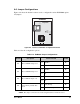
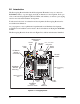
B.1.1 Prototyping Board Features
• Power Connection—A a 3-pin header is provided for connection to the power supply.
Note that the 3-pin header is symmetrical, with both outer pins connected to ground and
the center pin connected to the raw V+ input. The cable of the AC adapter provided
with the North American version of the Development Kit is terminated with a header
plug that connects to the 3-pin header in either orientation. The header plug leading to
bare leads provided for overseas customers can be connected to the 3-pin header in
either orientation.
Users providing their own power supply should ensure that it delivers 8–24 V DC at
8 W. The voltage regulators will get warm while in use.
• Regulated Power Supply—The raw DC voltage provided at the 3-pin header is
routed to a 5 V switching voltage regulator, then to a separate 3.3 V linear regulator.
The regulators provide stable power to the RCM4000 module and the Prototyping
Board.
• Power LED—The power LED lights whenever power is connected to the Prototyping
Board.
• Reset Switch—A momentary-contact, normally open switch is connected directly to the
RCM4000’s /RESET_IN pin. Pressing the switch forces a hardware reset of the system.
• I/O Switches and LEDs—Two momentary-contact, normally open switches are con-
nected to the PB4 and PB5 pins of the RCM4000 module and may be read as inputs by
sample applications.
Two LEDs are connected to the PB2 and PB3 pins of the RCM4000 module, and may
be driven as output indicators by sample applications.
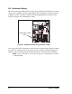
• Prototyping Area—A generous prototyping area has been provided for the installation
of through-hole components. +3.3 V, +5 V, and Ground buses run around the edge of
this area. Several areas for surface-mount devices are also available. (Note that there
are SMT device pads on both top and bottom of the Prototyping Board.) Each SMT pad
is connected to a hole designed to accept a 30 AWG solid wire.
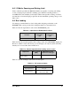
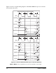
• Module Extension Header—The complete non-analog pin set of the RCM4000 mod-
ule is duplicated at header J2. Developers can solder wires directly into the appropriate
holes, or, for more flexible development, a 2 × 25 header strip with a 0.1" pitch can be
soldered into place. See Figure B-4 for the header pinouts.
• Analog Inputs Header—The complete analog pin set of the RCM4000 module is
duplicated at header J3. Developers can solder wires directly into the appropriate holes,
or, for more flexible development, a 2 × 7 header strip with a 0.1" pitch can be soldered
into place. See Figure B-4 for the header pinouts.
• RS-232—Two 3-wire or one 5-wire RS-232 serial ports are available on the Prototyp-
ing Board at header J4. A 10-pin 0.1" pitch header strip installed at J4 allows you to
connect a ribbon cable that leads to a standard DE-9 serial connector.