
International User's Manual Network Adapter RCM4000


User’s Manual 55
Reads the state of differential analog input channels and uses the previously set calibration constants to
convert it to volts.
PARAMETERS
channel is the analog input channel number (0 to 7) corresponding to LN0_IN to LN7_IN
gaincode is the gain code of 0 to 7.
RETURN VALUE
A voltage value corresponding to the voltage differential on the analog input channel.
ADOVERFLOW (defined macro = -4096) if overflow or out of range.
ADTIMEOUT
(defined macro = -4095) if conversion is incomplete or busy-bit timeout.
SEE ALSO
anaInCalib, anaIn, anaInmAmps, brdInit
float anaInDiff(unsigned int channel,
unsigned int gaincode);
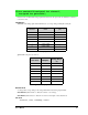
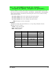
channel DIFF
Voltage Range
(V)
0 +AIN0 -AIN1
-22.5 to +22.5
*
* Accessible on Prototyping Board.
1 +AIN1 -AIN1 —
2 +AIN2 -AIN3 -22.5 to +22.5*
3 +AIN3 -AIN3 —
4 +AIN4 -AIN5 -22.5 to +22.5*
5 +AIN5 -AIN5 —
6 +AIN6 -AIN7 —
7 +AIN7 -AIN7 —
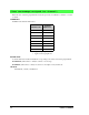
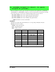
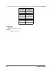
Gain Code Multiplier
Voltage Range
*
(V)
* Applies to Prototyping Board.
0 ×1 -22.5 – +22.5
1 ×2 -11.25 – +11.25
2 ×4 -5.6 – +5.6
3 ×5 -4.5 – +4.5
4 ×8 -2.8 – +2.8
5 ×10 -2.25 – +2.25
6 ×16 -1.41 – +1.41
7 ×20 -1.126 – +1.126