
International User's Manual Network Adapter RCM4000

User’s Manual 47
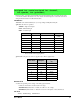
5.2.5 Analog Inputs (RCM4000 only)
Use this function to configure the A/D converter. This function will address the A/D converter in
Register Mode only, and will return an error if you try the Direct Mode. Appendix B.4.3 provides
additional addressing and command information.
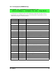
unsigned int anaInConfig(unsigned int
instructionbyte, unsigned int cmd, long baud);
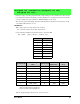
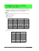
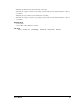
ADS7870 Signal ADS7870 State RCM3400 Function/State
LN0 Input AIN0
LN1 Input AIN1
LN2 Input AIN2
LN3 Input AIN3
LN4 Input AIN4
LN5 Input AIN5
LN6 Input AIN6
LN7 Input AIN7
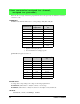
/RESET Input Board reset device
RISE/FALL Input Pulled up for SCLK active on rising edge
PIO0 Input Pulled down
PIO1 Input Pulled down
PIO2 Input Pulled down
PIO3 Input Pulled down
CONVERT Input Pulled down when not driven
BUSY Output PE0 pulled down; logic high state converter is busy
CCLKCNTRL Input Pulled down; 0 state sets CCLK as input
CCLK Input Pulled down; external conversion clock
SCLK Input PB0; serial data transfer clock
SDI Input PC4; 3-wire mode for serial data input
SDO Output PC5; serial data output /CS driven
/CS Input BUFEN pulled up; active-low enables serial interface
BUFIN Input Driven by VREF
VREF Output Connected to BUFIN and BUFOUT
BUFOUT Output Driven by VREF