
International User's Manual Network Adapter RCM4000


20 RabbitCore RCM4000
3.2.2 Serial Communication
The following sample programs are found in the SAMPLES\RCM4000\SERIAL folder.
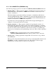
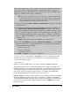
• FLOWCONTROL.C—This program demonstrates how to configure Serial Port D for
CTS/RTS with serial data coming from Serial Port C (TxC) at 115,200 bps. The serial
data received are displayed in the STDIO window.
To set up the Prototyping Board, you will need to tie TxD and RxD
together on the RS-232 header at J4, and you will also tie TxC and
RxC together using the jumpers supplied in the Development Kit as
shown in the diagram.
A repeating triangular pattern should print out in the STDIO window.
The program will periodically switch flow control on or off to demonstrate the effect of
no flow control.
If you have two Prototyping Boards with modules, run this sample program on the
sending board, then disconnect the programming cable and reset the sending board so
that the module is operating in the Run mode. Connect TxC, TxD, and GND on the
sending board to RxC, RxD, and GND on the other board, then, with the programming
cable attached to the other module, run the sample program.
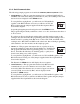
• PARITY.C—This program demonstrates the use of parity modes by
repeatedly sending byte values 0–127 from Serial Port C to Serial Port D.
The program will switch between generating parity or not on Serial
Port C. Serial Port D will always be checking parity, so parity errors
should occur during every other sequence.
To set up the Prototyping Board, you will need to tie TxC and RxD together on the
RS-232 header at J4 using one of the jumpers supplied in the Development Kit as
shown in the diagram.
The Dynamic C STDIO window will display the error sequence.
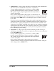
• SIMPLE3WIRE.C—This program demonstrates basic RS-232 serial
communication. Lower case characters are sent by TxC, and are
received by RxD. The characters are converted to upper case and are
sent out by TxD, are received by RxC, and are displayed in the
Dynamic C STDIO window.
To set up the Prototyping Board, you will need to tie TxD and RxC together on the
RS-232 header at J4, and you will also tie RxD and TxC together using the jumpers
supplied in the Development Kit as shown in the diagram.
J4
RxC TxC
GND
TxD RxD
J4
RxC
RxD GND
TxD
TxC
J4
RxC TxC
GND
TxD RxD