
Specifications


Digi m10 Hardware Reference v 1.20
Digi International, Inc. © 2009
Page 11 of 36
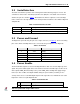
Figure 3: Pin Assignment
Table 1: Connector Pins on the Digi m10
Pin Name Description
Digital I/O
Direction
Comments
1 VCC Supply
2 GND Ground
3 VCC Supply
4 GND Ground
5 PWR_EN Digi m10 Power Enable Input
Pulled low
using 47KΩ
6 GND Ground
7 RX
3.3 V RS232 Interface. Host controller to the Digi
m10
Input
8 TX 3.3V RS232 Interface. Digi m10 to host controller.
Output
9 SA Satellite Available Output
10 DA Data Available Output
11 Dbg_Tx 3.3V UART Interface Digi M10 to Debug Port Output
12 Dbg_Rx 3.3V UART Interface Debug Port to Digi m10 Input
13 RTS 3.3V UART Interface. Host controller to Digi m10 Input
14 CTS 3.3V UART Interface. Digi m10 to Host controller Output