
Specifications


Digi m10 Hardware Reference v 1.20
Digi International, Inc. © 2009
Page 10 of 36
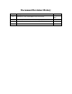
Figure 2: Digi m10 Pin Numbering
The connector provides the necessary interface signals to communicate over a 3.3V TTL level
serial link and to power Digi m10. Basic communication can be established using the Tx & Rx
lines and the remaining signals provide additional handshaking (RTS/CTS), status (SA/DA) and
debug information (Dbg_Tx/Dbg_Rx) as described in the following sections.
Refer to
Table 1 for details. The Digi m10 can be connected to the host PCB using a 14-pin
SAMTEC 1mm pitch, stacker header connector (MW-07-03-G-D-147-065-P).