
Installation guide


Chapter 6: Installing Modules 61
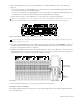
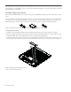
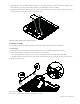
3 Connect power and Ethernet to the connectors on the bottom of the display. Use the black Cable Harness power cable and
12-inch Ethernet cable you fed through the Back Tie Plate of each chassis in “Short Ethernet Cables for Knob Modules and Dis-
play Modules” on page 48.
4 Repeat the previous steps to install other Display Modules.
5 After all Display Modules are in place, go to Chapter 7, “How to Proceed” to complete the installation of your S6 system.
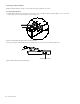
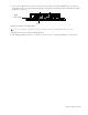
Connectors on the bottom of the Display Module
Do not connect anything to the USB ports unless directly instructed to do so by an Avid Authorized Service provider.
Gigabit
Power
Ethernet RJ45