
Installation guide

Chapter 6: Installing Modules 53
Chapter 6: Installing Modules
This chapter shows you how to install and connect hardware modules into an assembled frame.
The basic steps for installing and connecting modules are as follows:
• Populate the first (left-most) chassis with all its modules.
• Install and connect modules in each chassis, front-to-back.
• Repeat to populate all other chassis with modules.
• Install Display Modules, if any.
• Install Fill Panels into any empty slots.
• Install a Compression Panel into each chassis to complete the assembly.
About These Instructions
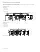
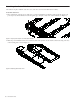
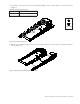
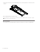
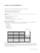
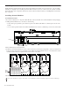
The following instructions show an S6 M40–24–5 system as an example configuration (see Figure 32). This configuration provides
24 fader strips with 5 knobs per strip, plus a standard master section module configuration.
• 3 Fader Modules
• 3 Process Modules
• 3 Knob Modules
• 1 Master Module (M40)
• 1 Automation Module
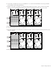
This example configuration has the master section modules at the far right of the system with faders to the left. However, modules
can be arranged in many different positions as explained in Chapter 2, “Modules and Configuration Overview.” Your exact instal-
lation procedure will differ slightly from this example configuration depending on your system and desired arrangement of mod-
ules (all variations are noted as appropriate).
The Master Module requires several special connections that are unique from other modules. Be sure to follow all instructions
carefully.
Figure 32. Arrangement of modules in example S6 M40 24-5 system