
Installation guide

Chapter 5: Installing the Power Strip, PSUs, Switches, and Cables 45
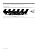
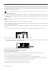
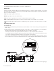
3 Run the Cable Set through the (lower) triangular cable guides in the Rear Panel brackets to the furthest (left- or right-most) chas-
sis, as shown in Figure 18. (For systems with more than three chassis, see “Installing Cable Sets in Large Configurations” on
page 46.)
4 Connect the other ends (1–5) to the Ethernet terminal ports (1–5) on the outside back of the chassis
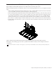
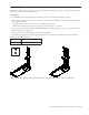
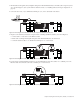
5 Repeat for other Cable Sets and chassis (except the chassis containing any Ethernet switches) as shown in Figure 19:
• Connect cables 1–5 of the next set to the Ethernet switch.
• Run the cable set through the triangular cable guides in the Rear Panel Mounts to the next chassis.
• Connect the Cable Set cables 1–5 to the Ethernet terminal ports 1–5 on each chassis.
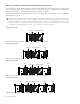
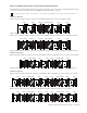
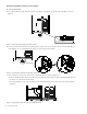
6 For the chassis containing the Ethernet switch(es), use the Small Cable Set and connect cables 1–5 to available ports on the
Ethernet switch, and connect the other ends to terminal ports 1–5 on the chassis.
Figure 18. Connecting the first Cable Set to the first (left-most) chassis Ethernet terminal ports
Figure 19. Connecting the next Cable Set to the right-most chassis Ethernet terminal ports
Figure 20. Connecting a Cable Set Small to the Ethernet terminal ports on the back of the switch chassis
12 3 4 5
12 3 4 512 3 4 5
12 3 4 5
12 3 4 5
12 3 4 512 3 4 5
12 3 4 5
12 3 4 5
12 3 4 512 3 4 5 12 3 4 5