
Installation guide


S6 Installation Guide40
Installing the Ethernet Switch
The capacity (number of ports) and number of switches in your system depends on the number of chassis and module in your sys-
tems. Systems with fewer chassis and modules might only require a single 16-port switch, larger systems a 24-port switch, while
the largest systems (23 or more modules) require two Ethernet switches. Ethernet switches are installed into specific chassis and
secured with the included tie-down bracket.
To install the Ethernet switch(es):
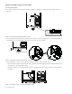
1 Unpack the Ethernet switch(es), the included Ethernet cables and tie-down bracket with fasteners. Although the switch includes
a standard power cable in the Ethernet Switch box, you must use one of the additional power cables (C14 type) included in the
Bolster package.
2 Attach the included feet to the bottom of the Ethernet switch. (Very important!)
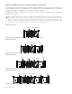
3 Refer to the diagrams in “Ethernet Switch and PSU Placement per System Configuration” on page 37 to determine switch and
PSU placement for your configuration.
4 After determining placement for your configuration, install the Ethernet switch(es) in the appropriate chassis by doing the fol-
lowing
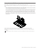
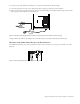
• If necessary, disconnect the power harness from the terminal port on the inside of the Back Tie Plate (see Figure 9).
• Place the switch in the chassis so that its ports face the back of the frame (the ports should be visible through the horizontal
opening in the Back Tie Plate as shown in Figure 10).
Connecting Power to the Ethernet Switch
To connect power to the Ethernet switch:
1 Take the male AC power cable provided with the Ethernet switch(es), disconnect it from the switch and set it aside.
2 Locate the additional AC (C14) power cable included in the Bolsters package.
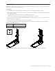
3 Feed the switch end through the opening of the Back Tie Plate and connect it to the Ethernet switch(es).
• If you are assembling a Frame Chassis Small, the power cable needs to be placed underneath the switch (it is a tight fit).
4 Connect the other end to the power strip you installed at the beginning of this chapter.
5 If your system includes two Ethernet switches, repeat for the other switch.
6 Set the tie-down bracket aside (it is installed after all cables are in place).
If your system includes a Producer’s Desk option, see the Producer’s Desk Guide for switch, PSU, and cabling instructions.
Do not use the power cable provided in the Ethernet switch box (it has a standard male IEC connector which will not work with
the S6 Power Strip).
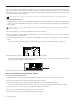
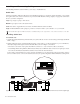
Figure 9. Power harness (make sure it is disconnected before installing Ethernet switch)
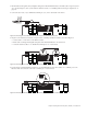
Figure 10. Back view of a chassis with an Ethernet switch