
Installation guide

Chapter 5: Installing the Power Strip, PSUs, Switches, and Cables 39
Switch and PSU Placement for Custom S6 Configurations
These diagrams show switch and PSU placement for example systems that are six or more chassis in width. Install and secure units
as shown for your frame size, then proceed to “Installing and Connecting Cabling” on page 44.
6-Chassis Systems
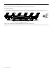
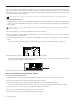
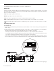
Figure 4 shows an example six-chassis system such as an M40-40-5 that requires a single 24-port Ethernet switch.
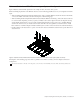
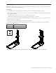
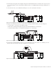
Figure 5 shows a different example six-chassis system such as an M40-40-9-D. This configuration uses two Ethernet switches.
7-Chassis Systems
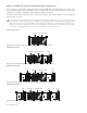
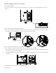
Figure 6 shows an example seven-chassis system such as an M40-48-9-D. This configuration uses one 16- and one 24-port switch.
9-Chassis Systems
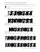
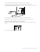
Figure 7 shows an example nine-chassis system such as an M40-64-9. This configuration uses one 16- and one 24-port switch.
Figure 8 shows another nine-chassis system such as an M40-64-9-D. This configuration uses two 24-port switches.
If your system includes a Producer’s Desk option, see the Producer’s Desk Guide for switch, PSU, and cabling instructions.
Figure 4. Ethernet switch and PSUs in a 40-fader system requiring one switch
Figure 5. Ethernet switches and PSUs in a 40-fader system with two switches, a 16-port in chassis 1 (far left) and a 24-port in chassis 4
Figure 6. Ethernet switches and PSUs in a 48-fader system requiring two switches, a 16-port in chassis 2 and a 24-port in chassis 6
Figure 7. Ethernet switches and PSUs in a 64-fader system requiring two switches, a 16-port in chassis 3 and a 24-port in chassis 7
Figure 8. Ethernet switch and PSU placement for a 64-fader system with two 24-port switches, one in chassis 3 and the other in chassis 7
PSUEthernet switchPSUs (2) PSUPSU PSU
PSU
24-port switch
PSUs (2)
PSUPSUs (2)
16-port switch
24-port switch
PSUPSUPSUs
16-port switch
PSU
PSUs
24-port switch
PSUPSU PSUs
PSUs
16-port switch
PSUPSU PSU
24-port switch PSUPSU PSUsPSUs 24-port switch PSUPSU PSU