
Installation guide

S6 Installation Guide38
Switch and PSU Placement for Avid-Configured S6 Systems
These diagrams show switch and PSU placement for all frame widths available with Avid-configured S6 systems, which range in
size from 8-fader/two chassis (such as an S6 M10-8-5) up to 32-fader/five chassis (such as an M40-32-9-D). For larger (custom)
configurations see Chapter 5, “Installing the Power Strip, PSUs, Switches, and Cables”.
You will first place the units in their chassis, then connect their power cables. After units are installed, proceed to “Installing the
Ethernet Switch” on page 40.
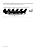
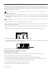
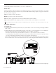
2–Chassis Systems
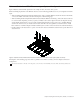
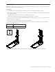
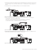
3–Chassis Systems
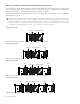
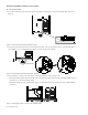
4–Chassis Systems
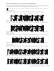
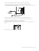
5–Chassis Systems
When assembling a Reduced Depth Frame (Frame Chassis Small) the Ethernet switch must go in the same chassis as the master
section modules. Depending on where you place your Master section (left-to-right) in the frame, the diagrams showing switch and
PSU placement may not be appropriate for Reduced Depth Frame systems. Just be sure to install the Ethernet switch in the same
chassis as your master section modules, then follow the other guidelines to determine where to install PSUs. Cable Sets of suffi-
cient length are included with all systems to make connections between the switch and all chassis.
Ethernet switch and PSU placement for an two-chassis, 8-fader system (cables not shown)
Ethernet switch and PSU placement for a three-chassis, 16-fader system (cables not shown)
Ethernet switch and PSU placement for a four-chassis, 24-fader system (cables not shown)
Ethernet switch and PSU placement for an example five-chassis, 32-fader system (cables not shown)
Ethernet switch
PSUs (2)
Ethernet switch
PSUs (2)
PSU
Ethernet switch
PSUs (2)
PSUPSU
PSU
Ethernet switch
PSUs (2)
PSUPSU