
Installation guide


Chapter 5: Installing the Power Strip, PSUs, Switches, and Cables 35
Chapter 5: Installing the Power Strip, PSUs, Switches,
and Cables
This chapter explains how and where to install the Power Strip, Ethernet switches and Power Supply Units (PSUs), how to connect
Ethernet throughout the system using the included Cable Sets, and how to connect power to PSUs and the switch.
As recommended in Chapter 1, identify and organize the packages containing the Power Strip, Ethernet switch(es), PSUs, and Ca-
ble Sets.
Overview
The basic steps are:
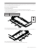
1 Install the Power Strip (see “Installing the Power Strip” on page 36).
2 Determine switch and PSU placement for your configuration as described in “Ethernet Switch and PSU Placement per System
Configuration” on page 37.
3 Place the Ethernet switch in the appropriate chassis (see “Installing the Ethernet Switch” on page 40).
4 Place PSUs in the appropriate chassis (see “Installing PSUs” on page 41) and secure them using the included tie-down brackets.
5 Attach the special AC power cables (included) to the Ethernet switch and PSUs (see “Installing the Ethernet Switch” on
page 40). Do not connect power cables to the Power Strip yet.
6 Install Cable Sets to connect the Ethernet switch(es) to each chassis, then install the single Ethernet cable for workstations (see
“Installing and Connecting Cabling” on page 44).
7 After all Ethernet cables are in place, connect the AC cables for the switch and PSUs to the power strip.
8 Install the Ethernet switch tie-down bracket to secure it to the chassis.
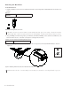
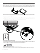
Figure 1. Packages for electrical components (left-to-right, Power Supplies, Ethernet switch, Power Strip (PDU), and Cable Sets). Type and
number of packages varies depending on configuration