
Installation guide


S6 Installation Guide8
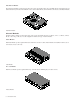
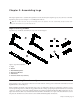
Module Layout
This section describes the arrangements of modules front-to-back in their chassis, and chassis left-to-right in the frame.
Front-to-Back Module Arrangements
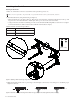
In most configurations, master section modules are installed together in a single chassis with the Master Module above the Auto-
mation Module. They do not have to be in the same chassis, but for simplicity this guide shows them installed together.
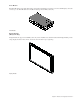
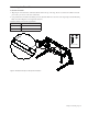
Channel modules are usually installed together to provide the fader strips in a system. The Fader Module is installed in slot 1, Pro-
cess Module in slot 2, and Knob Module in slot 3. Frame Chassis Small support one Knob Module per chassis; the Frame Chassis
Large support up to two Knob Modules per chassis. M40-based systems also support Display Modules. Not all slots need to contain
modules. Fill panels are available to cover unused slots.
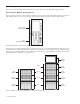
Master section modules in a Frame Chassis Small
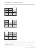
Channel modules in a Frame Chassis Small (left) and a Frame Chassis Large (right)
Slot 1
Slots 2 and 3
Automation Module
Master Module
Fader
Knob
Process
Slot 1
Slot 3
Display
Slot 2
Slot 4
Module
Module
Module
Fader
Knob
Process
Module
Module
Module
Knob
Module
Module