S6 Installation Guide For Avid S6 M10 and S6 M40 Systems
Legal Notices © 2014 Avid Technology, Inc., ("Avid"), all rights reserved. This guide may not be duplicated in whole or in part without the written consent of Avid.
Contents Part I Introduction Chapter 1. Introduction . . . . . . . . . . . . . . . . . . . . . . . . . . . . . . . . . . . . . . . . . . . . . . . . . . . . . . . . . . . . . . . . . . . . . . . . . . 1 Overview of Installation . . . . . . . . . . . . . . . . . . . . . . . . . . . . . . . . . . . . . . . . . . . . . . . . . . . . . . . . . . . . . . . . . . . . . . 2 What’s Included . . . . . . . . . . . . . . . . . . . . . . . . . . . . . . . . . . . . . . . . . . . . . . . . . . . . . . . . . . . . . .
Part III Modules Chapter 5. Installing the Power Strip, PSUs, Switches, and Cables . . . . . . . . . . . . . . . . . . . . . . . . . . . . . . . . . . . . . 35 Overview . . . . . . . . . . . . . . . . . . . . . . . . . . . . . . . . . . . . . . . . . . . . . . . . . . . . . . . . . . . . . . . . . . . . . . . . . . . . . . . 35 Installing the Power Strip . . . . . . . . . . . . . . . . . . . . . . . . . . . . . . . . . . . . . . . . . . . . . . . . . . . . . . . . . . . . . . . . . . .
Part I: Introduction
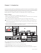
Chapter 1: Introduction Avid® S6 is a professional, modular, ergonomically designed control surface for Avid Pro Tools® and other EUCON™-compatible DAWs (Digital Audio Workstations). S6 is flexible and scalable, letting you choose the best system for your needs. Many different configurations are possible with different numbers of faders, knobs, and displays. All systems let you place the master section in any position, left-to-right, within a frame.
Overview of Installation 1 Determine module layout (“Modules and Configuration Overview” on page 5) 2 Assemble the frame • Assemble Legs if your system includes them (“Assembling Legs” on page 13) • Assemble the Frame Chassis kits (“Assembling Frame Chassis” on page 19) 3 Install modules • Install the Ethernet switch, power supplies and cables (“Installing the Power Strip, PSUs, Switches, and Cables” on page 35) • Install modules (“Installing Modules” on page 53) 4 Start up your system to confirm mod
Optional The following items are recommended and can be purchased separately: • UPS (Uninterruptable Power Supply), power conditioner/timer, or other power management system • USB computer keyboard and mouse/trackball (the Master Module provides a touchscreen keyboard, but you might prefer to use a dedicated keyboard/mouse/trackball for some administrative or troubleshooting tasks) System Requirements and Compatibility Avid can only assure compatibility and provide support for hardware and software it has
About This Guide This guide explains how to assemble your Avid S6 system.
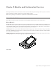
Chapter 2: Modules and Configuration Overview This chapter identifies each of the S6 modules, and tells you how and where they can be arranged within a system. Use this information to determine your module layout before proceeding with the assembly. There are two primary types of modules in a system, Master modules and Channel modules. Master Section Modules The S6 Master Module and S6 Automation Module are often installed in the same chassis to form a master section.
Automation Module The Automation Module provides transport and locate controls, the Attention fader strip, Jog/Shuttle wheel, a numeric keypad, and additional Soft Keys. The Automation Module is most often installed directly below and in the same chassis as the Master Module. Automation Module Channel Modules Channel modules combine to form the fader strips of the system, and include the S6 Fader Module, S6 Process Module, S6 Knob Module, and S6 Display Module.
Knob Module Each Knob Module provides eight channel strips, each with four dual-function (rotate/press) encoders, OLED displays, and other controls. Up to two Knob Modules can be installed in the larger chassis M40 systems only. Knob Module Display Module (M40 Systems Only) Display Modules are supported on S6 M40 systems only, and are installed above channel modules. Each Display Module provides a large display that shows names, meters, waveforms, and other data for up to eight strips.
Module Layout This section describes the arrangements of modules front-to-back in their chassis, and chassis left-to-right in the frame. Front-to-Back Module Arrangements In most configurations, master section modules are installed together in a single chassis with the Master Module above the Automation Module. They do not have to be in the same chassis, but for simplicity this guide shows them installed together.
Left-to-Right Chassis and Module Arrangements Channel sections and the master section modules can be arranged in any order, left-to-right. For example, in an S6 M10–16–5 system (16 faders with five knobs per strip) the master section modules can be located in three possible locations, as shown below.
10 S6 Installation Guide
Part II: Frames
Chapter 3: Assembling Legs This chapter explains how to assemble the Leg Frames for the S6. Not all systems require Legs. If your system does not include Leg Frames, please proceed to Chapter 4, “Assembling Frame Chassis.” Make sure you have at least one other person available if you need to lift, turn, or move the system during and after assembly. Components and systems are heavy! Team lift, always. Unpack the Leg Frames Unpack the Legs and Beams and identify the components shown in Figure 1.
Attaching the Back Beam Attaching the back Beam: 1 Place one of the Beams on the floor to determine how far apart the Legs need to be. Have someone help hold the components while you position the Beams on the Legs and attach the fasteners. 2 Attach the back beam by doing the following (see Figure 2): • Put the first Beam across the back of the Legs. Align the pins on the underside of the Beams with the holes in the top of the Legs.
Attaching the Front Beam To attach the front Beam: 1 Align the pins on the underside of the Beam with the holes in the top of the Legs. Be sure to orient the front Beam so that the pins on the top are closer to the center of the frame. 2 Using four fasteners and washers (included) per mount, attach the Beam across the front of the Legs using two Beam Mounting Plates as shown in Figure 4. Do not tighten the fasteners.
Attaching the Back Corner Brackets To attach the Back Corner Brackets: 1 Attach the Back Corner Brackets as shown in Figure 5 using four fasteners and washers (included) per bracket. Align the pins on the brackets with the holes in the top of the Legs. Fasteners, Washers, and Tools for Back Corner Brackets Fastener M5x15 Washer M5 Tool M4 Hex (Not to scale) Figure 5.
Attaching the End Shelves To attach the End Shelves: Using four fasteners and washers per side, attach the Left and Right End Shelves to the Legs as shown in Figure 6. Fasteners, Washers, and Tools for End Shelves Fastener M5x15 Washer M5 Tool M4 Hex (Not to scale) Figure 6. Attaching the Left End Shelf (Right End Shelf shown attached) Leveling the Leg Frame To level the back legs: Use the 13 mm open end wrench (included with the Legs) and adjust the back leveling feet (see Figure 7).
To level the front legs: Use an M4 Hex to adjust the front leveling feet from above. Turn clockwise to raise, counterclockwise to lower. Figure 8. Front leveling foot How to Proceed When your Leg Frames are assembled, proceed to Chapter 4, “Assembling Frame Chassis.
Chapter 4: Assembling Frame Chassis This chapter explains how to assemble the chassis and attach them to each other to form the frame of your S6 system. As recommended in Chapter 1, identify all Frame component kits (Chassis kits, Side Covers, Bolster, and Rear Panel kits) as shown in Figure 9. Figure 9.
Frame Chassis Kit Components Frame Chassis Kits are either Large (extended depth) or Small (reduced depth). The contents of both kits are the same. 1 2 3 Figure 10. Frame Chassis kit components (Cable Harnesses not shown) 1 – Chassis (See Figure 11) 2 – Back Foot 3 – Tie-down Bracket for PSU 4 – T-strip 5 – Display Module Filler 6 – Cable Harnesses (not shown) 7 – Fasteners: Phillips and Hex fasteners (not shown) B E A C D Figure 11.
Assembling the Chassis If you have not already done so, unpack all Frame Chassis and fasteners and arrange them next to each other on your work surface. The Chassis kits also include tie-down brackets (for PSUs), a T-Strip, and Display Module Fillers. Set these aside for now. Figure 12. Four Frame Chassis Small Attaching the End Side Wall To attach the end Side Wall: 1 Open the S6 Side Covers package and unpack the included Side Wall. Figure 13.
3 Secure the Side Wall to the Back and Front Tie Plates using Hex fasteners. Fasteners and Tools for Back and Front Tie Plates to Side Wall Fasteners M5x8 FHCS (7760-30553-00) Tool M3 Hex (Not to scale) Figure 15. Attaching the end Side Wall to the Back and Front Tie Plates 4 If your system does not include Legs, proceed to Step 6.
6 Move the next chassis into position so that the right edge of its Chassis Bottom Plate sits on top of the left edge of the first chassis as shown in Figure 17. Figure 17. Attaching the first two chassis (top view, at left, and front view, at right) 7 If your system includes a Leg Frame, attach the second chassis to the Beams and secure loosely using more of the Hex fasteners included with the Beams as shown in Figure 16. Tighten them enough to hold the chassis in place, but do not tighten them fully.
Secure the Back and Front Tie plates of the second chassis to the first chassis using Hex fasteners as shown in Figure 19. 9 Fasteners and Tools for Back and Front Tie Plates to Side Wall Fasteners M5x8 FHCS (7760-30553-00) Tool M3 Hex (Not to scale) Figure 19. Securing the Back and Front Tie Plates of the first chassis to the Side Wall of the second chassis (cables not shown) 10 Fully tighten all screws holding the Side Walls to the Chassis Bottom Plate (Phillips), Back and Front Tie Plates (Hex).
Attaching the Back Feet After assembling the chassis, attach the back feet. • One Back Foot is included with each Frame Chassis Kit. • Two Back Foot Mounting Spacer bars and an additional Back Foot are included in the Side Covers kit. Installing Back Foot Mounting Spacers To install the two Back Foot Mounting Spacers: 1 Locate the Back Foot Mounting Spacer bars (2) included in the Side Covers kit.
Attaching the Back Feet To attach the Back Feet: 1 Unpack each Back Foot and screws from each Frame Chassis kit. Locate and unpack the additional Back Foot in the Side Covers package. Back Feet Back Feet and Fasteners 7020-38616-00 Back Foot, Mounting Bracket, and screws The number of back feet is equal to the number of chassis (width) of the frame, plus one. For example, a 16-fader S6 system has a frame width of three chassis, so it requires four back feet (3+1=4).
• All other Back Feet are mounted to adjacent Back Tie Plates as shown in Figure 23. Figure 23. Attaching a Back Foot to two adjacent Back Tie Plates Leveling the Chassis After the feet are mounted to the frame, check that the chassis is level. If one or more feet are too short or too tall, raise or lower them in order to level and support the back of the frame. You can adjust the feet using an M3 hex driver as shown in Figure 24 Figure 24.
Attaching the Bolster The Bolster is a one-piece reinforced arm rest that matches the width of your configuration. The wide, padded surface provides a comfortable work area, and its one-piece design provides additional structural support along the front of the control surface. The Bolster hangs along the front edge of the frame and is secured from below using fasteners. To attach the Bolster: 1 Locate the Bolster and remove it from its packaging, being careful to locate the included fasteners.
Installing Display Module Mounting Brackets If your system includes Display Modules, install their mounting brackets as explained in the following instructions. (The Display Modules are attached to the mounting brackets later.) If your system does not include Display Modules, proceed to “Installing Rear Panel Mounting Brackets” on page 30. If your system includes one or more Display Modules, do the following: 1 Unpack all S6 Display Modules and locate their mounting brackets.
Installing Rear Panel Mounting Brackets Rear Panels support and conceal cables. Rear Panels consist of two pieces, a lower bracket that mounts to the frame, and an upper, hinged cover that attaches to the bracket. The upper covers have open corners to guide power and Ethernet for Display Modules (if your system includes Display Modules), and cutouts to support S6 Options (such as the Speaker Bridge and VESA Monitor mount). Figure 27. Rear Panel Lower Mounting Bracket (left) and Upper Cover (right).
Installing Side Covers Side Covers (one Left, and one Right) consist of two pieces: a mounting plate that attaches to the frame, and an outer panel that attaches to the mounting plate and secured from inside the chassis. Attaching the Side Mounting Plates To attach the Side Mounting Plates: 1 Unpack the Side Covers package and identify the Left and Right Side Mounting Plates and their fasteners.
How to Proceed After assembling the chassis that form your system frame, proceed to Chapter 5, “Installing the Power Strip, PSUs, Switches, and Cables.
Part III: Modules
Chapter 5: Installing the Power Strip, PSUs, Switches, and Cables This chapter explains how and where to install the Power Strip, Ethernet switches and Power Supply Units (PSUs), how to connect Ethernet throughout the system using the included Cable Sets, and how to connect power to PSUs and the switch. As recommended in Chapter 1, identify and organize the packages containing the Power Strip, Ethernet switch(es), PSUs, and Cable Sets. Figure 1.
Installing the Power Strip The power strip is placed across the Rear Panel brackets, behind the center of the frame. To install the power strip: 1 Standing behind the middle of the frame, place the power strip on the Rear Panel brackets so that it sits on the angled arms of the brackets as shown in Figure 2. The power strip’s sockets should face up and towards the front of the frame. . (Not to scale) Figure 2.
Ethernet Switch and PSU Placement per System Configuration Figure 3 illustrates switch and PSU placement for an example 32-fader (five chassis wide) system. When determining the placement of the Ethernet switch, observe the following guidelines based on your configuration and frame depth. • When assembling an Extended Depth Frame (Frame Chassis Large), install the Ethernet switch in the chassis in the middle, or next to the middle of the frame as shown in the diagrams on the following pages.
Switch and PSU Placement for Avid-Configured S6 Systems These diagrams show switch and PSU placement for all frame widths available with Avid-configured S6 systems, which range in size from 8-fader/two chassis (such as an S6 M10-8-5) up to 32-fader/five chassis (such as an M40-32-9-D). For larger (custom) configurations see Chapter 5, “Installing the Power Strip, PSUs, Switches, and Cables”. You will first place the units in their chassis, then connect their power cables.
Switch and PSU Placement for Custom S6 Configurations These diagrams show switch and PSU placement for example systems that are six or more chassis in width. Install and secure units as shown for your frame size, then proceed to “Installing and Connecting Cabling” on page 44. If your system includes a Producer’s Desk option, see the Producer’s Desk Guide for switch, PSU, and cabling instructions.
Installing the Ethernet Switch The capacity (number of ports) and number of switches in your system depends on the number of chassis and module in your systems. Systems with fewer chassis and modules might only require a single 16-port switch, larger systems a 24-port switch, while the largest systems (23 or more modules) require two Ethernet switches. Ethernet switches are installed into specific chassis and secured with the included tie-down bracket.
Installing PSUs Each chassis requires one PSU to supply power for modules. PSUs are installed alone or in pairs and secured with the tie-down brackets (one is included in each Chassis package). To install PSUs: 1 Unpack all PSUs from their packaging, and collect their special AC cables included in the Bolster package. 2 Place one PSU in each chassis but do not place one in the same chassis as the Ethernet switch. Instead, put two PSUs in an adjacent chassis.
Connecting Power Cables to the PSUs To connect power to PSUs: 1 If you haven’t already, feed the DC power cable from each PSU out through the opening in the Back Tie Plate as shown in Figure 12. Figure 12. Power cable terminal through the Back Tie Plate 2 Connect the cable terminal end from the outside back of the chassis to the power terminal connector on the Back Tie Plate as shown in Figure 13. Use a small flathead screwdriver to secure the plug to the terminal. Figure 13.
4 Locate the power cables included in each PSU box, as well as those included in the Bolster package. 5 Connect the appropriate end of the power cables from the Bolster package to the PSU (repeat for all PSUs). 6 Feed the other end of the AC cables through the opening in each Back Tie Plate and run them through the upper (square) cable guide openings in the Rear Panel as shown in Figure 15. Figure 15.
Installing and Connecting Cabling After installing the Ethernet switch and PSUs you are ready to install Cable Sets. Cable Sets Cable Sets are bundles of Ethernet cables that connect the Ethernet switch(es) to each chassis. Cables are labeled (1–5) to identify and organize cables and connections. Cable Sets are provided in Small, Medium, and Large (lengths), in appropriate combinations based on your frame configuration. Large Long enough to span up to three chassis.
3 Run the Cable Set through the (lower) triangular cable guides in the Rear Panel brackets to the furthest (left- or right-most) chassis, as shown in Figure 18. (For systems with more than three chassis, see “Installing Cable Sets in Large Configurations” on page 46.) 4 Connect the other ends (1–5) to the Ethernet terminal ports (1–5) on the outside back of the chassis 1 2 3 4 5 11 22 33 44 55 1 2 3 4 5 Figure 18.
Installing Cable Sets in Large Configurations Refer to the following diagrams for Cable Set installation examples for four-chassis (24-fader) and larger system configurations. Numbers in the diagram indicate the type of Cable Set installation. 4-Chassis Systems (See Figure 21): 1 Cable Set Large 2 Cable Set Medium 3 Cable Set Small 3 1 1 2 3 4 5 2 1 2 3 4 2 5 1 2 3 4 1 5 Figure 21. Cable Sets in a 24-fader (four chassis) system.
6-Chassis Systems Systems with 40 faders (six chassis) require slightly different cabling depending on the number of modules in the system (which determines whether the system needs one or two Ethernet switches). Example 1 (Single Ethernet Switch: see Figure 23): 1 Cable Set Large 2 Cable Set Medium 3 Cable Set Small 3 1 1 2 2 1 Figure 23.
Short Ethernet Cables for Knob Modules and Display Modules (Systems with Two Knob Modules per Chassis and/or Display Modules Only) If your system includes two Knob Modules in any chassis, take one of the included 12-inch long Ethernet cables and connect one end of it to an available port on the interior of the Back Tie Plate. Repeat for all chassis that will have two Knob Modules.
Installing the Tie-Down Bracket for the Ethernet Switch After all Ethernet and power cables are installed, secure the Ethernet switch to its chassis using its included tie-down bracket as shown in Figure 26. The bracket is included in the Ethernet Switch package, and its fasteners are provided in a small plastic bag taped to the bracket. Fasteners, and Tools for Ethernet switch tie-downs Fasteners M3x6 Tool #1 Phillips (Not to scale) Figure 26.
Attaching the Outer Side Covers After cables are in place, install the outer side covers (outer side covers must be installed before modules). To attach the Side Covers: 1 Before attaching the outer Side Covers, make sure to route the single Ethernet (workstation) cable and the AC supply to the power strip across the Rear Panels and down through the gap to the right (or left) of the outer Rear Panels (see Figure 27). Figure 27.
3 From the inside of the chassis, use four of the included flathead Phillips screws to secure the Side Cover to the frame as shown in Figure 29. Fasteners and Tools for the Side Covers Fasteners M4x14 FHPH Tool #2 Phillips (Not to scale) Figure 29. Securing the left Side Cover 4 Make sure power and Ethernet cables are not in the way, then take the right Side Cover and attach it to the right mounting plate as shown in Figure 30. Figure 30.
5 From the inside of the chassis, use four more flathead Phillips screws to secure the right Side Cover to the frame as shown in Figure 30. Figure 31. Attaching the right Side Cover (Bolster not shown) Never attempt to move or lift a chassis (any size) by the Side Covers, Bolster, or Rear Panels (they can break). Move or lift while holding on to the metal chassis (frame) instead.
Chapter 6: Installing Modules This chapter shows you how to install and connect hardware modules into an assembled frame. The basic steps for installing and connecting modules are as follows: • Populate the first (left-most) chassis with all its modules. • Install and connect modules in each chassis, front-to-back. The Master Module requires several special connections that are unique from other modules. Be sure to follow all instructions carefully. • Repeat to populate all other chassis with modules.
Installing Modules Install all modules beginning with the left-most chassis. Begin with the slot/module closest to the front (slot 1). In our example S6 M40 24-5 configuration we are installing channel modules in the left-most chassis, so the first (front-most) module to install is a Fader Module. In other configurations the left-most chassis could be for Master modules (see “Installing Master Section Modules” on page 57).
4 Locate the Process Module and connect power and Ethernet to it as you did for the Fader Module. Use the longest available power and Ethernet cables in that Cable Harness. 5 Install the connected Process Module in slot 2 behind the Fader Module, being careful to orient it correctly and seat it fully against the top edge of the Fader Module.
8 If your system includes two Knob Modules in a Frame Chassis Large, do the following: • Connect power to the second Knob Module. • Take one of the included 12-inch Ethernet cables and connect it to an available chassis port at one end, and connect the other end to the Knob Module. • Install the second Knob Module in slot 4, directly above the first Knob Module.
Installing Master Section Modules Installing the Automation Module is nearly identical to installing a Fader Module. Installing the Automation Module To install the Automation Modules: 1 2 If you haven’t already done so, unpack the Automation Module and Master Module. Hold the Automation module above its chassis and do the following: • Connect the longest 2-pin Molex power cable to the DC input on the side of the module. • Connect the longest Ethernet cable to the Ethernet port on the side of the module.
Installing the Master Module Installing a Master Module is similar to other modules but requires additional connections. To install the Master Modules: 1 Hold the Master Module above the chassis and connect two of the 2-pin Molex cables in the Cable Harness, one to each of the two DC inputs on the side of the module as shown in Figure 33. Figure 33.
3 After connecting Ethernet to the primary (side panel) Ethernet port of the Master Module, do either of the following (see Figure 35): • If you are connecting S6 to an existing DHCP Server on your network, connect another Cable Harness Ethernet cable to Ethernet port 1 (left) on the back panel of the Master Module.
Installing Fill Panels Fill Panels are available in metallic or acrylic finishes, and come in two sizes to fill small and large slots. Fill Panel Large Same size as Fader Module for filling slot 1. Fill Panel Small Same size as Process and Knob Modules for filling slots 2, 3, or 4. To install Fill Panels: Unpack the Frame Panel packages, and install them to cover any empty slots. Fill Panels slide into place, just like modules.
3 Connect power and Ethernet to the connectors on the bottom of the display. Use the black Cable Harness power cable and 12-inch Ethernet cable you fed through the Back Tie Plate of each chassis in “Short Ethernet Cables for Knob Modules and Display Modules” on page 48. Gigabit Ethernet RJ45 Power Connectors on the bottom of the Display Module Do not connect anything to the USB ports unless directly instructed to do so by an Avid Authorized Service provider.
62 S6 Installation Guide
Chapter 7: How to Proceed After assembling the system and installing modules, use the instructions in this chapter to do all of the following: • Start up the system for the first time to confirm power and Ethernet (see “Starting Up and Shutting Down” on page 63). • Activate and Register your purchase, then download and install any available updates (see “Activate and Register” on page 63). • Add the final hardware components to finish the frame (see “Complete the Hardware Assembly” on page 64).
Complete the Hardware Assembly After confirming power and Ethernet connections, add Compression Panels and T-Strips to secure the modules in place, and install upper Rear Panels to conceal cables. Installing Compression Panels After you have installed all modules and covered any empty slots with Fill Panels, install a Compression Panel at the top of each chassis. Compression Panels are spring-loaded panels that seal the top of each chassis and hold the modules in place.
5 Take the Master Compression Panel (included in the Side Covers package) and hold it so that the side with the springs faces the back of the frame. If you have a Frame Chassis Small, use the smaller Master Compression Panel. 6 Holding the panel at an angle, place the spring side of the panel against the back of the chassis. Apply enough pressure to compress the springs, then lower the front edge and snap it into place. 2 1 Figure 38.
Attaching the Upper Rear Panels After installing and connecting all modules, attach the upper Rear Panels. Figure 40. Upper Rear Panel To install the upper Rear Panels: 1 Take one of the upper Rear Panels and lower it into place so that its mounting screw lines up with the receiver on the lower panel, then secure its thumb-screw into the threaded receiver on the Rear Panel Mounting Bracket. Figure 41.
Updating S6 System Software This section provides instructions for acquiring and installing updated S6 Master Module software (MTMApp). Required Materials The following are required to transfer the MTMApp software to your S6 system: • A USB flash drive (not included), formatted as NTFS, FAT32 or other Windows 8-compatible (Mac formatted drives are not supported) Do not use the included System Restore USB drive! Use a separate USB flash drive.
7 After the installer has completed you will be prompted to restart the Master Module. Click Yes to restart. 8 If you are prompted to update module firmware, do the following: • Navigate to the Settings > Surface page and press Update. If no Update option is displayed either the system hasn't completely booted yet, or a module is selected on that screen. Wait for the system to finish starting up, and be sure no module is selected on-screen.
Part IV: Appendices
Appendix A: Expanding or Disassembling S6 This section provides disassembly instructions for modules, PSUs, Ethernet switches, and chassis (frame) components. Use these instructions when preparing to expand or move your system, or while troubleshooting. Important Do not attempt to lift or move an assembled S6 desktop system if it is five or more chassis in width to avoid risk of damage to the frame.
6 Remove Fill Panels (if any). 7 Remove modules by doing the following: • If you are removing all modules from a chassis, start at the top module (usually a Knob Module). If you are removing just one module, slide the other modules towards the back of the control surface. • Slowly lift the module out of the chassis, being careful not to strain the power or Ethernet cables. • Disconnect power, Ethernet and any other cables connected to the module (such as USB).
Appendix B: Compliance Environmental Compliance Disposal of Waste Equipment by Users in the European Union This symbol on the product or its packaging indicates that this product must not be disposed of with other waste. Instead, it is your responsibility to dispose of your waste equipment by handing it over to a designated collection point for the recycling of waste electrical and electronic equipment.
EMC (Electromagnetic Compliance) Avid declares that this product complies with the following standards regulating emissions and immunity: • FCC Part 15 Class B • EN 55022 Class B • AS/NZS CISPR 22 Class B • CISPR 22 Class B • EN 55103-1, Class E2 and E3 • EN 55103-2, Class E2 and E3 FCC Compliance for United States Communication Statement NOTE: This equipment has been tested and found to comply with the limits for a Class B digital device, pursuant to Part 15 of the FCC Rules.
Safety Compliance Safety Statement This equipment has been tested to comply with USA and Canadian safety certification in accordance with the specifications of UL Standards: UL 60065 7th Ed., 2007-12-11, CAN/CSA C22.2 No. 60065-03, 1st Ed, 2006-04 +A1:2006, EN 60065:2002 + A1:2006 + A11:2008, IEC 60065:2001 + A1:2005 + A2:2010. Avid Technology Inc., has been authorized to apply the appropriate NRTL mark on its compliant equipment.
15) For products that are a Mains powered device: The equipment shall not be exposed to dripping or splashing and no objects filled with liquids (such as vases) shall be placed on the equipment. Warning! To reduce the risk of fire or electric shock, do not expose this equipment to rain or moisture. Do not defeat the safety purpose of the polarized or grounding-type plug. A polarized plug has two blades with one wider than the other. A grounding type plug has two blades and a third grounding prong.
Avid Technical Support (USA) Product Information 2001 Junipero Serra Boulevard Daly City, CA 94014-3886 USA Visit the Online Support Center at www.avid.com/support For company and product information, visit us on the web at www.avid.