
Specifications


Table Of Contents
- About This Manual
- 1.0 Introduction
- 2.0 Installation
- 3.0 Configuration Settings
- 4.0 Calibration
- 5.0 Scale Operations
- 5.1 Weight Unit Switching
- 5.2 Entering Tare Weights
- 5.2.1 One-Touch Tare, Tare Unknown
- 5.2.2 Digital Tare, Tare Weight Known
- 5.2.3 Tare Addition or Subtraction
- 5.2.4 Tare Exchange
- 5.3 Toggling Between Gross and Net
- 5.4 Entering Unit Weights
- 5.4.1 Unit Weight Operation by Sampling
- 5.4.2 Unit Weight Operation by Key Entry
- 5.5 Part Accumulation and Negative Counting - Without Recalling an Item Code
- 5.5.1 Part Accumulation
- 5.5.2 Negative Counting
- 5.5.3 Clearing Accumulated Data
- 5.6 Toggle Between Scales
- 5.7 Adding Parts To and Subtracting Parts From Inventory
- 5.7.1 Adding Parts to Inventory
- 5.7.2 Subtracting Parts From Inventory
- 5.7.3 Sample, Count and Print a Label
- 5.7.4 Scan ID Bar Code, Count and Print a Label
- 6.0 Scale Programming
- 6.1 Item Code Storage
- 6.1.1 Checking Memory Status
- 6.1.2 Program ID Code, Unit Weight, Tare Weight, Label Format, Part Name, Part Number, Lot Number, Location, Inventory Quantity, Threshold, and Setpoints
- 6.1.3 Delete Item Memory
- 6.2 Using Item Codes in Normal or Operation Mode
- 6.2.1 Recalling Numeric Item Codes using Item Code Number
- 6.2.2 Re-Computing Item Code Unit Weight
- 6.2.3 Quick Add Item to Memory
- 6.2.4 Tare Override
- 6.2.5 Inventory Operations Related to the Item Code Quantity
- 6.2.6 Delete Item Memory
- 6.3 Setting Tare in Operation Mode
- 6.3.1 One Touch Tare
- 6.3.2 Digital Tare (When Tare Weight is Known in Advance)
- 6.3.3 Tare Value Exchange (Tare Addition or Subtraction)
- 6.4 Setting a Lot Number
- 6.5 Setting a Sequence Number
- 7.0 External Printers, Barcode Scanners, Keyboards and Platforms
- 7.1 Connecting External Printers
- 7.1.1 SPEC Settings for External Printers
- 7.1.2 Connecting the Printer to the RS-232C Port
- 7.1.3 Eltron Printers
- 7.1.4 Epson Printers
- 7.2 Connecting a Barcode Scanner
- 7.2.1 Header Codes
- 7.2.2 Z Commands via Barcodes
- 7.2.3 Configuring the RS232C Port for a Scanner
- 7.2.4 Connecting the Scanner to the RS232C Port
- 7.2.5 Configuring the Keyboard Port for a Scanner
- 7.2.6 Programming the QSC-6000 Plus Quickscan RS232C Scanner
- 7.2.7 Programming the QuickScan Keyboard Wedge Scanner
- 7.3 Connecting the IBM Keyboard
- 7.4 Connecting an External Platform
- 8.0 Job Sequence Programming
- 9.0 Password Protecting the Programming Functions
- 10.0 DC-100 Error Message List
- 11.0 DC-100 Limited Warranty
28 DC-100 Operation Manual
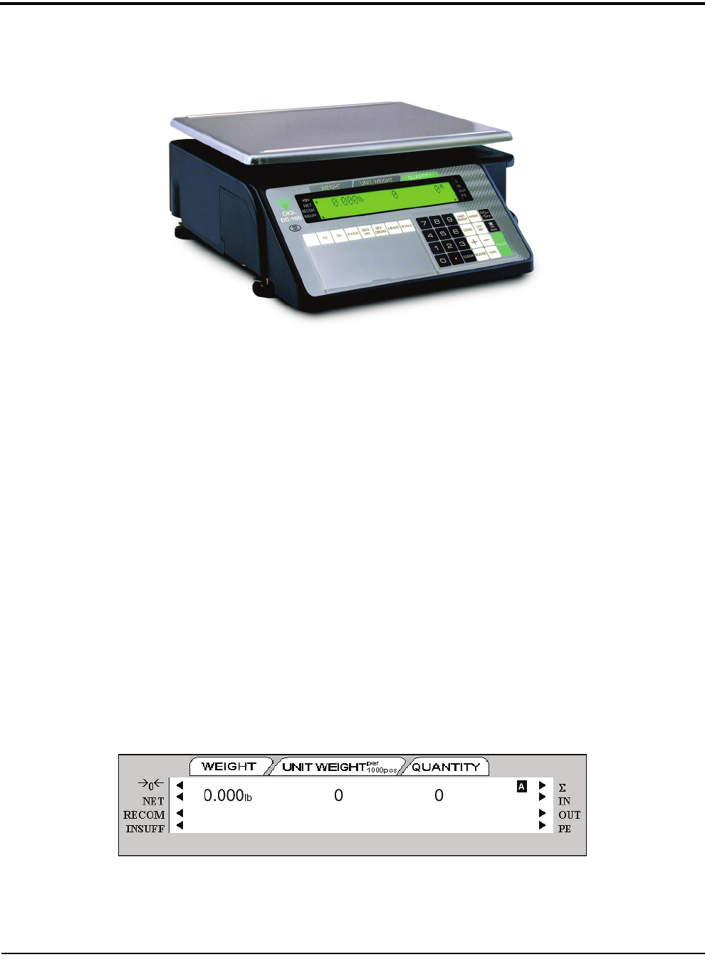
5.0 Scale Operations
The following paragraphs contain detailed operator instructions for the DC-100 counting scale (see Figure 5-1).
Included are instructions to enter tare weights, toggle between net and gross weight, enter unit weights, perform
inventory accumulation and reduction, and toggle between scales. All operator instructions are conducted with
the scale in the operation mode that is the weighing or normal mode.
Figure 5-1. DC-100 Counting Scale
Counting scale accuracy is primarily determined by the following factors:
• Sample size (number of pieces)
• Total sample size as a percentage of full scale capacity
• Piece-to-piece weight variation
As a general rule when determining sample size of fairly uniform pieces, the larger the sample size the greater
the total sample weight, therefore, the better the counting accuracy. Selecting the smallest capacity scale that can
obtain the highest counting resolution should be considered, but should not sacrifice the capacity required for the
heaviest container of parts. For this kind of application, a dual-platform scale may be the best selection.
There is a direct relationship between piece-to-piece weight variation (non-uniformity) and counting accuracy.
Therefore, elimination of the piece-to-piece weight variations can be accomplished by:
1. Isolating the sample used to calculate the unit weight and use the same sample to re-check the scale.
2. Recalculating the unit weight from lot-to-lot of parts. Parts manufactured on one machine may vary
slightly from another machine relative to weight.
3. Tightening the manufacturing tolerances on the parts reduces piece weight variations and increases count
accuracy.
The Stand-By Screen
The starting point for using the scale in operation mode is the stand-by screen. At the stand-by screen the WEIGHT,
UNIT WEIGHT,
and QUANTITY displays show zeroes and the annuciator for the platform you are using is illuminated
(A, B, C or D).
From the stand-by screen you can perform all of the basic weighing, counting and inventory operations of the
scale.