COMDIAL DIGITECH Digital Telephone System System Manual This publiiion is @icable to the following COmmoR #IQ@mmt: - CQ408 Rev. A and l8ter ( -‘.CX!6$6 Rev. A and kter ’ 4$&Z@ Rev. A and later PKOlO-004 12 MI 66-083.
Table Of Contents TABLE OF CONTENTS CHAPTER 1 SYSTEM OVERVIEW . . . . . . . . . . . . . . . . . . . . . . . . . . . . . 1-l SECTION 1 INTRODUCTION . . . . . . . . . . . . . . . . . . . . . . . . . . . . . . . . . . . . . . . . . l - l SECTION 2 PUBLICATIONS OVERVIEW . . . . . . . . . . . . . . . . . . . . . . . . . . . . . . . . . . 1-2 ..l- 2 ManualScope . . . . . . . . . . . . . . . . . . . . . . . . . . . . . . . . . . . . . . . . . . . . . . . . . . . . l-2 Related Publications . . . . . . . . . . .
IMI 66-r- Table Of Contents 2-6 Conferencing - Multiline . . . . . . . . . . . . . . . . . . . . . . . . . . . . . . . . . . . . . . . . . . . . . . . . . . . . . . . . . . . . . . . . . . . . . . . . . . . . . . . . . . . . . . . . . . . . . . . 2-6 Conferencing - Unsupervised ..26 DataSecurity . . . . . . . . . . . . . . . . . . . . . . . . . . . . . . . . . . . . . . . . . . . . . . . . . . . . . . . . . . . . . . . . . . . . . . . . . . . . . . . . . . . . . . . . . . . . . . . . . . .
.lJll otPutr3 Table Of Contents Originating Denied . . . . . . . . . . . . . . . . . . . . . . . . . . . . . . . . . . . . . . . . . . . . . . . . . . . PBXICENTREXICO Compatible . . . . . . . . . . . . . . . . . . . . . . . . . . . . . . . . . . . . . . . . . . . . Personalized Ringing Tone . . . . . . . . . . . . . . . . . . . . . . . . . . . . . . . . . . . . . . . . . . . . . . Pooled Line Access . . . . . . . . . . . . . . . . . . . . . . . . . . . . . . . . . . . . . . . . . . . . . . . . . .
IMI 66,’ Table Of Contents SECTION 2 OPTION INSTALLATION DETAILS . . . , . . . , . . . . . . . . . . . . . . . . . . . . . . 3-14 Key System/Hybrid Configuration . . . . . . . . . . . . . . . . . . . . . . . . . . . . . . . . . . . . . . . . . . . Power Failure Station Connections . . . . . . . . . . . . . . . . . . . . . . . . . . . . . . . . . . . . . . . . . . Auxiliary Equipment Interface . . . . . . . . . . . . . . . . . . . . . . . . . . . . . . . . . . . . . . . . . . . . .
Table Of Contents . . . . . . . . . . . . . . . . . . . . . . . . . . . . . . . . . . . . . . . . . . . . System COS Menu Selections . . . . . . . . . . . . . . . . . . . . . . . . . . . . . . . . . . . . . . . . . . . . . . Line COS Menu Selections Station COS Menu Selections . . . . . . . . . . . . . . . . . . . . . . . . . . . . . . . . . . . . . . . . . . . . . . . . . . . . . . . . . . . . . . . . . . . . . . . . . . . . . . . . . . . . . . Toll Restriction Table Administration .4-87 .4-88 .4-89 .
IMI 66 ’ Table Of Contents LIST OF ILLUSTRATIONS . . . . . . . . . . . . . . . . . . . . . . . . . . . . . . . l-5 Outline Dimensions - Common Equipment . . . . . . . . . . . . . . . . . . . . . . . . . . . . . . . . l-6 Outline Dimensions - Station Equipment l-7 Station Images . . . . . . . . . . . . . . . . . . . . . . . . . . . . . . . . . . . . . . . . . . . . . . . . . . . . . . . . . . . . . . . . . . . . . . . . . . . . . . . . . . . . . . . . 3-2 Mounting Dimensions . . . . . . . . . . . . . . . .
System Overview CHAPTER 1 SYSTEM OVERVIEW SECTION 1 INTRODUCTION The digital telephone system is an expandable communications system with many attractive characteristics including the following: feature access, line access, messaging and more. Programmed buttons helps station users eliminate manual dialing errors. Unitized base unit which includes all system features. The base unit is full featured and self-contained. Service observing.
System IMI 66. Overview SECTION 2 PUBLICATIONS OVERVIEW MANUAL SCOPE l This publication contains a technical discussion of the digital telephone system. Included in this manual is the following information: Chapter 1, System Overview: This chapter provides a generalized understanding of the system, an explanation of the supporting documentation, and a summary of the equipment hardware.
System . ..a. au-u83 Overview SECTION 3 HARDWARE SUMMARY The digital telephone system consists of an electronic Key Service Unit (KSU) base unit, usually referred to as common equipment, optional expansion modules to extend station and line capacities as required, a software cardridge containing the operating System programming, dedicated digital electronic key telephones, and interconnecting wiring consisting of small, 2-- or 4--conductor, twisted-pair cable.
System The image designations refer to the number of programmable buttons located below the keypad, including the hold and intercom buttons, as opposed to the number of programmable buttons located above the keypad. l IMI 66 Overview available in both monitor and speakerphone versions. l The 10x14 image provides a moderate sized line button matrix along with a moderate sized priority line button grouping. This image is best suited for typical work area stations.
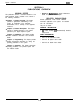
System +I- &Line, Mtatlon Base Unit {- 16.50 7- 7 . 4 4 -I+- Id ,-I +I-- “. “:~:x:%:~:::~:z: :~:~:“:::::::m:x:::~: gg:““:“:t:.c:“:n:zm: ... . .. . . . . . . . x . I==/ I 26:35 I I 26.25 1 Z? 1 I : q 0 +- 2.13 &Llne, 16Statlon Base Unit 14.8 7 - 16.50 - I ! I 1 i ?6 1 +-I -=I+, t- t - 7 . 4 4 + -I- 0 27 2 2 + 2.89 -c-l %-Line. 3%Station Base Unit Figure 1-l.
System Overview l-6
_- d33 System Overview J 0 I’r0 0 0 0 0 0 0 t 0 0 0 0 0 l-7
IMI 66-u,.
IMI 66-083 dysrem Overview OPERATlNG ENVIRONMENT 32-122 degrees F (O-50 degrees C) TEMPERATURE: HUMIDIlY: 90 percent relative, non-condensing TEFlMlNATlONS Standard 50-pin male connectors for connection to external distribution field.
IMI 66-083 DeSCriDtiOn of Svstem Feat3 CHAPTER 2 DESCRIPTION OF SYSTEM FEATURES transferred. On transferred calls, the transferee is associated with the call record. On incoming calls, the last user active on a call is the one that is associated with the costed call record. The system can be programmed to place an appropriate message on the display to remind users of LCD speakerphones to enter an account code.
IMI 66-083 -rVI @on Of System Features No class of service programming is required to enable this feature. use of the add-on conference feature. In the non-private mode, another station with that line appearance can gain access at the same time (sometimes known as common line pickup). A line is specified as private or non-private through the line class of service programming. Through station class of service programming, a line can be made non-private at a particular station.
Description Of System Feat! lMl66-083 activated when station port 17 rings or when ringing sent to the paging port. iS When programmed for station port 7 7 ringing, an external device is often used to provide loud ringing. When programmed for paging port ringing, an external paging amplifier is usually employed. The system supplies ringing tones to the paging port along with the relay closures. The ringing tones can be sent to the input of an external paging amplifier.
IMI 66-083 _-, +ion of System Features Detailed report sorted by stations l Detailed report sorted by account codes 0 Line summary report l Department summary report l A general output of all records l Upon completion of report printing, all records used for the reports can be deleted. Any call records created between the time the report printout was started and completed will not be deleted.
Description Of System Feat1 P IMI 66-083 be effected. If the other station does not have access to the incoming line, transfer can still take place using the system transfer feature. For a screened transfer, a call is transferred to another station with a pre-transfer announcement by the transferring patty. Transferring calls is accomplished with the TRANSCONF button. Also refer to the discussion titled: Call Transfer- Unscreened.
8. lMl66-083 __, ,,.rtion Of System Features DELAYED RINGING CONFERENCING - ADD-ON With this feature, a station, operating in a private mode, can add up to four other stations to an outside call. CONFERENCING - MULTILINE This feature will allow one station to access up to four outside lines at the same time resulting in a conference arrangement. Conferencing is established through the use of the TRANSKONF button.
lMl66-083 Other Calls: This is a summation of the time spent on outgoing call activity, incoming call activity on non-department lines, plus all intercom call activity. On-Duty Time: The on-duty time includes a summation of idle time, department call time, wrap-up time, and other call time. Off-Duty Time: The time that a station spent in a do not disturb mode. While in a do-notdisturb condition, a station is not available tc receive calls.
,&Ion Of System Features Further, the system camp-on feature cannot be used to camp-on to a department. Subsequent calls to a department on a particular line always try the next station in the department from whichever station serviced the last call on that line. This means that if department stations 15 and 16 are programmed to answer line 1, and station 15 services a call, the next line 1 call will ring at station 16.
Description Of System Feats lM166-083 to the DISD assist station if one is programmed; otherwise, the line is dropped. If the assist station is busy (call will camp-on at the assist station) or lf the assist station does not answer before the transfer recall timeout period, the system will return the caller to DISD dial tone. If extension number dialing is not completed within the dial time limit this time, the line is dropped.
lMl66-083 ..tron Of System Features operations can be performed. Station class of service programming allows certain buttons to be programmed as dynamic line buttons line class of service programming arranges a line port for external paging interface. FEATURE INHIBIT END-TO-END SIGNALLING ON INTERCOM After an intercom call has been established, the system can continue to send dialing signals (DTMF tones) through the intercom path.
Description Of System Featf lMl66-083 re-locating the station and line wiring. Line and station class of service programming are used to reassign stations and lines. Also refer to the discussion titled, Auxiliary Ringer Interface. FLEXIBLE STATION NUMBERING PLAN The system supports a flexible station numbering plan for individual stations. Each station can be programmed to respond to the dialing of any available number between 10 and 7999.
lMl66-083 -. #,.&on Of System Features always automatically replace a previously dialed number. Upon command, the system will choose a Line and redial the saved number. The system will first choose the prime line if assigned and idle. If it is busy or unavailable, the system will choose any line assigned to idle line preference. If they are unavailable, the system will chose the last line used at the station. If it is busy, no further choice is made. No class of service is required.
Description Of System Feat,. lMl66-083 ‘. programming provides a station with the ability to originate a message waiting signal and is used to create a central message desk. MODULAR WIRING AND JACKSR- OR 4-CONDUCTOR WIRE SYSTEM The system can be completely interconnected by employing industry standard 50-pin connectors and modular plug/jack combinations. Station wiring is small, 2conductor, twisted-pair cable throughout the system.
lMl66-083 .,,tron Of System Features off hook. Prime line pickup may be pre-empted by preselecting another line before lifting the handset. lf the prime line is ringing, lt is automatically answered by lifting the handset. Prime line automatic is assigned t0 a station through station class of service programming. PRIVACY - DESIGNATED PROGRAMMABLE BUlTON Stations can be programmed to provide a privacy button. If a line is private, a user can press the privacy button to change it into a non-private one.
lMl66-083 on a call. A station being operated in a handsfree mode cannot receive a SOHVA Wflh SOHVA, the announcement is delivered and responded to in a secure manner that prevents the distant party from hearing either the announcement or the response. The announcement is preceded with a tone alert and is delivered to the handset receiver of the telephone. The announcing caller receives a tone alerting them that they are making a SOHVA call. Response to the announcement can be verbal or non-verbal.
lMl66-083 .&ion of System Features SELF DIAGNOSTICS Each station can execute a self test when so enabled. This test verifies processor, indicator, and tone functions. SERVICE OBSERVING Service observing allows a third party to enter an in-progress call in an unannounced muted mode to monitor the conversation. There will be no warning tones sounded when the call entry is made.
Description Of System Fea: lMl66-063 TIMED HOLD RECALL SUBDUED RINGING When a station is busy on a call and another call comes to the same station, the ringing of the second call will automatically be subdued to a lower volume. After a call has been on hold for a programmed length of time the system will recall the station that placed the call on hold. The system class of service programming sets the timed hold recall time period.
,lron Of System Features local calls and will only take effect when the system is placed in the night transfer (of ringing) mode. Therefore, even though toll calls can be made from this station during daytime operation, no toll calls can be made from it when the attendant programs the system for nighttime operation using the night transfer of ringing feature. NOTE This night mode roll restriction table assignment should nor be confused with the night transfer (of ringing) feature.
Installs IMI 66-083 CHAPTER 3 INSTALLATION SECTION 1 STANDARD INSTALLATION DETAILS MOUNTING CONSIDERATIONS The common equipment cabinet should be attached vertically to any sturdy, flat surface. It may be vertically rack-mounted if desired. The cabinet must be located within six feet of a proper electrical outlet. The system requires a dedicated 117VAC 15 AMP circuit, with a third-wire ground, supplied to a standard electrical outlet (NEMA 5-15R).
- - don IMI 66-083 4-Line, &Station Base Unit &Line, 1 &Station BaseUrlR 16-Line, 32-Station Base Unit Figure 3-l.
Instal’. IMI 66-083 The minimum battery backup time for a fully configured system can be calculated. The formula for doing this is: AC POWER CONNECTION Employ a dedicated 117VAC third-wire ground, supplied to outlet (NEMA 515R) for the power connection is illustrated below. l 15 AMP circuit, with a a standard electrical AC power connection. A in Figure 3-2 shown A plug-in power line surge protector should be installed between the power cord and the AC outlet.
FUSE : 4-LINE, 8-STATION BASE UNIT: I AMP 250V SLOW BLOW FUSE 8 - L I N E , I6-STATION B A S E U N I T : 3A 2 5 0 V S L O W B L O W F U S E I6-LINE, 32-STATION BASE UNIT: 3A 250V SLOW BLOW FUSE P L U G I N POKR LI NE SURGE PROTECTOR A’ TYPICAL) DEDICATED I I7VAC 15 AM’ NEM4 5-15R -------e-J I I I INTERFACE ICONNECTOR llFOR O P T I O N A L ~COMDIAL ,EXTERNAL IBATTERY TYPICAL-EARTH GROUND (METAL COLD WATER PIPE, B U I L D I N G FRAME,..ETC.l - SEE NOTE. Figure 3-2.
lnstall-s IMI 66-083 LINE CONNECTIONS Connections between the common equipment and the stations are typically via type 66M-xx connector block!; which are cable connected to the common equipmer,t 50-pin male connector. The connector block is, in turn, wired to modular jacks which the stations connect to through the line cord. The maximum distance allowed from the common equipment to the stations is 1000 feet using #24 gauge, twisted-pair cable.
.-- .- don IMI 66-083 Table 3-1 LJNE JACK 1 Line Connectlons PIN NO . Auxlllaty 1 (Llne 2) TIP Llne 2 TlP Llne 1 TIP L i n e 1 RING Llne 2 RING Auxlllaty 1 (Line 2) RING Auxiliary 2 (Line 4) TIP 4 Lh, 8 Sta. Baaa Unlt 8 Unr, 16 Sta. Base Unlt 1 6 Lhr, 32 Sta Base Unlt Llnn A TIP Line 3 TIP F-t+B Llno, 16 Sta. Base Unit 16 Line, 32 Sta. Base Unlt ++- --I++ --I+--k5 6 Llna, 32 Sta.
IMI 66-083 Table 3-2.
-. IMI 66-083 ,,dn Table 3-3. Jl Station COnneCtiOnS (&Line, 16~Station Base Unit) : rnuyEcnnNc STA. STA PAI WIRE COLOR 1 11 2 3 .Y B L”YT\-“L”L BLUE-BLACK BLACK-ORANGE nRANP.E-RI AI-Y I I IO II 12 I PIP-NAI WV” 11 37 2’; 23 “,“l.mb PATH SIGNAL i3 74 DATU 3-8 i YI.bb,.
instalk? IMI 66-083 . Table 34a. Jl Staion Connections (16-Line, 32-Station Base Unit) ._N 13 I28 I5 I SIGNAL I GREEN 12 I .-. . IOWN 4 . . - - . . . . .E.Sl-ATE _. ._ : 5 29 4 30 7 8 Q SIGNAL GREEN PATH SIGNAL fi GREEN I I- 16 131 Ill i SIGNAL I 1 14 I~i GREEN I 15 4RANGE 17 132 113 i SIGNAL i GREEN I 16 . .-EN I8 133 I15 I SIGNAL I GREEN I 17 9 18 35 IQ RED-BROWN BROWN-RED RED-SLATE ~.-- --.._ 1 SLATE-RED 1 ~BLACK-BLUE ~-~.
- IMI 66-083 don Table 3-4b. 52 Statlon COnneCtiOnS (16-Line, 32-Station Base Unit) CONNECTIONS 1mcmob4 N26 . ;;EN iD IEEN iD IEEN iD IEEN ID .- 27 28 29 30 8 3EEN :n 31 -I 32 3 4 ‘LJ 3EEN 35 iN 36 iN 37 IN38 34 39 .N 40 1I SIGNAL 1 GREEN ---.
4-LINE, LINE JACKS 1 & 2 AUX LINE 2 LINE JACKS AUX LINE 4 8-STATION BASE UNIT I6-LINE, 32-STATION B A S E U N I T STATIONS 1 O-25 RS-232 DATA PO RS-232 DATA PO LINE JACKS 9 & LINE JACKS 11 & LINE JACKS 13 & 1 4 LINE JACKS 15 & 16 STATION 10-17, COMMON AUDIBLE, DATA PORT, STATION 17 AUDIBLE, POWER FAIL STATION, HYBRID STRAP LINE JACKS 7 & 6 LINE JACKS 5 8 6 LINE JACKS 3 & 4, AUX LINE 4 LINE JACKS 1 & 2, AUX LINE 2 POWER FAIL STATION MUSIC INTERFACE PAGING PORT BATTERY BACK-UP CONNECTOR GROUNDING TERMI
TO AUXILIMY JMH 4 TO AUXILIMY JAM( 2 AK: : TIP I TIP 2 WfTIPKJi 33 TIP 4 Figure 3-4.
IMI 66-083 Installat.
IMI 66-083 .rbn SECTION 2 OPTION INSTALLATION DETAILS KEY SYSTEM/HYBRID CONFIGURATION The systern can be configured to operate as either a key system or as a hybrid system. Configuration is by way of a wire strap connected as detailed below and illustrated in Figure 3-6. The common equipment is shipped from the factory as a key system (KF). To convert operation over to the hybrid (MF) system, add the strap.
Installa,. IMI 66-083 industry standard, single-line telephone, such as a Comdial model 2500-xx, can be connected to a power failure pair and used to provide communications capability until the AC power to the system is restored. POWER FAILURE STATION CONNECTIONS The system provides a tip and ring pair connected to line 1 as an emergency power failure circuit.
IMI 66-083 .ilon NOTE: When the auxiliary interface feature is being employed, the line to line port reassignment as discussed on pages 3-5 and 4- 19 works as described except in regard to line 2 and line 4. Line 2 can only be reassigned to line port 4 and line 4 can only be reassigned to line port 2 AtJXILIARY EQUIPMENT INTERFACE An industry standard non-electronic telephone device or a data device can be connected on a line ahead of the common equipment.
Installa+’ IMI 66-083 Selected Ports COMMON AUDIBLE AND AUXILIARY RINGING INTERFACE The station 17 audible terminals provide a dry-contact relay closure whenever ringing is sent to a programmable destination. Class of service programming is used to choose either the paging port or station port 17 as the ringing destination. Refer to page 4-13 for details. Relay closure dry-contact points are available for controlling external audible equipment. These contact closures track the pattern of the ringing .
IMI 66-083 Aon NOTE: This paging enable constant closure function overrides the ring pattern closure provided when ringing is sent to the paging port. See the previous titled Common Auciit& . . paragraph . . AndRlV. EXTERNAL PAGING INTERFACE A special transformer-isolated paging port is used to couple the system to an external paging amplifier.
Installa:. IMI 66-083 EXTERNAL PAGING INTERFACE - LINE PORT closure feature is not available for use with this installation. A line port can be configured by class of service programming to be an AUXILIARY port. As an AUXILIARY port, it can be used to couple a station to an external paging device. This coupling is done from any station with that line presence by pressing the proper line key to select the AUXILIARY port. DTMF tones or dial pulses can be dialed through the AUXILIARY port as needed.
... : IMI 66-083 -ion common equipment) connection to the device RTS (request-to-send) connection. DATA DEVICE CONNECTIONS ‘The sys?em provides two RS232 Data Ports for use. l l When a video display terminal (VDT) is used to perform class of service programming, connect it RS232 Data Port A. to When a serial data printer is used for SMDR, SMDA, and CCS printout, connect it to the RS232 Data Port B.
IMI66-083 Installat.
itrion IMI 66-083 MUSIC INTERFACE impedance of this input is approximately 500 ohms. Use the volume control on the music source to adjust the audio level of the music as required. If music is to be part of the system, connect a customer-provided music source to the common equipme,nt music interface jack (phono jack) provided for this puwse as shown below in Figure 3-13. The MUSIC SOURCE (FOR MUSIC ON tii&DFND BACKGROUND Figure3-13.
IMI 66-083 Instalk: SECTION 3 ADD-ON EXPANSION MODULES provides station ports 10 through 25 and lines 1 through 8. When installed, a 408 Expansion module will provide station ports 26 through 33 and lines 9 through 12 thus creating a twelve line by twenty-four station system. INTRODUCTION One or two optional add-on be installed on the common increase the line and station system.
IMI 66-083 Installation 4-LINE, 24-PORT SYSTEM &STATION BASE UNIT &LINES AND 16.STATIONS (BASE “NlT PLUS ONE EXPANSION MODULE) 36-PORT SYSTEM 12.LINES AND PI-STATIONS (BASE UNIT PLUS ONE EXPANSION MODULE) &LINE, l&STATION BASE UNIT 4&PORT SYSTEM l&LINES AND 3%STATIONS (BASE UNlT PLUS TWO EXPENSION MODULES) 2C-LINES AND40-STATIONS (BASE IJNlT PLUS ONE EXPANSION MODULE) 72.PORT SYSEM 24.LINES AND 4BSTATIONS (BASE UNlf PLUS TWO EXPANSION MODULES) Figure 3-14.
Installa-‘on IMI 66-083 Table 3-6. Statlon Connections - 408 Expansion Module sTA.l STA 1M 2M 3M 4M MOWN-WHITE WHITE-SLATE ISLATE-WHITE 4 30 5 9 10 PATH 5M 6M 7M 6M POWER STATION SLATE-VIOLET 3-25 NNECTIONS .
IMI 66-083 mstallat/$n 4. Push excess cable inside base unit housing through connector opening. INSTALLATION Each add-on expansion module measures 15.5 wide x -1.4 high x 1.6 wide and weighs approximately 4 pounds. The modules are designed to be attached to the base unit and connected to it via cabling. l 5. install expansion module in place on all four mounting holes. Be sure excess cable is not pinched between add-on module and base unit. 6. Pull module down to latch in place.
Installa’:on IMI 66-083 SECTION 4 SOmARE CARTRIDGE INTRODUCTION A plug-in module is required with the common equipment base unit to provide the following functions: Operating System Software Control Defauft To avoid any chance of electrostatic discharge damage to the software cartridge, avoid touching the connector with your fingers while handling it.
IMI 66-083 installation Figure 3-16.
lnstall.~tion IMI 66-083 SECTION 5 DATA COMMUNICATIONS WITH THE DIGITAL TELEPHONE SYSTEM Arrange both station-to-trunk and station-to-station data communications through the system stations, using a data device, a modem, and a data switch.
r- TELEPHONE JACK DATA JACK . I, / COMMON EQUIPMEN INTERCONNECT CABLE (Supplled Wlth Data Switch) LHANDSET JACK (SEE NOTE 1) .0. w TYPICAL DATA SWITCH (SEE TEXT) TELEPHONE HANDSET (SEE NOTE 1) TYPICAL DATA DEVICE (PERSONAL COMPUTER OR VDT) TYPICAL DATA MODEM NOTE 1: When the telephone Is equipped with a headset jack, the fe/ephone handset remains connected to the telephone and Is left on-hook. The accessory headset Is then connecfed to the handset/a& of the data switch.
Installation IMI 66-083 SECTION 6 SYSTEM CHECKOUT AND FAILURE ISOLATION INITIAL CONDITION The system operating features are set to default conditions at initial power-up. These conditions provide a basic operating system with a known set of parameters, and the system should be initially checked out with the default conditions in place. At any time while the system is operating, default conditions can be reset from station port 10 or 12 per the instructions provided in Chapter 4, Programming.
IMI 66-083 Installation SECTION 7 INSTALLER/USER INFORMATION REGARDING FCC RULES AND REGULATIONS This electronic key system complies with Federal Communications Commission (FCC) Rules, Part 68. The FCC registration label on the KSU contains the FCC registration number, the ringer equivalence number, the model number, and the serial number or production date of the system.
System Programrr>ng IMI 66-083 CHAPTER 4 SYSTEM PROGRAMMING SECTION 1 GENERAL INFORMATION Configuration programming is performed from station port 10 or station port 12. The programming station should be an LCD Speakerphone. Any digital telephone can be installed at station port 10 or 12 and used for programming but LCD feedback of the programming operations will not be available. Programming commands will not be accepted from any other station port in the system.
IMI 66-083 System’Programming SECTION 2 CLASS OF SERVICE PROGRAMMING Class of service programming is usually performed by the system installer. Class of service programming procedures provide the means for programming all of the system variables. The installer may elect to program only the line attributes and allow the remainder of the system variables to remain set to their defautt values. Perform class of service programming as shown below.
MASTER CLEAR The entire programming configuration, as discussed in the following programming procedures, can be defaulted to the factory settings at once using the Master Clear procedure. Not on/y does this action return ALL programmed variabbs to a known state of operatlon, It also clears all current/y stored autodial and speed dial numbers. FEATURE DESCRIPTION P G ENTRY CODE AND PROMPTING DISPLAY Base Level: The first step in any programming sequence is to enter the base level.
SYSTEM DEFAULTS l Mark the desired selections in the charts to record programming needs. Dial the feature code and then dial the selection code or press the programming button to program the selection. NOTE: A current program setting is indicated by a lighted Lf D next to fhe programfning button for that selection. When a toggle (on/oH) action is provided by a sing/e button, the lighted LED indicates an active feature.
SYSTEMCONFIGURATION Mark the desired selections in the charts to record programming needs. Dial the feature code and then dial the selection code or press the programming button to program the selection. IOZE: A current program setting is indicated by a lighted LED next to fhe pmgramming button for fhaf selection. When a fcggfe (on/ofl) acfion is provided by a sing/e button, the lighted LED indicates an active feature.
Press ITCM +# # 7 4 6 +k for base level. FEATURE DESCRIPTION ENTRY CODE AND PROMPTING DISPLAY Recall/Flash: A line disconnect 1. Dial 12 “RECALUFLSH XXXX” 2. Select time. “RECALUFLSH 0.08” - Dial 1 or Press Al. - Dial 2 or Press A2. WECALUFLSH 0.30” - Dial 3 or Press A3. WECALUFLSH 0.50” - Dial 4 or Press A4. “RECALUFLSH 0.60” - Dial 5 or Press A5. “RECALUFLSH 0.75” - Dial 6 or Press A6. “RECALUFLSH 0.88” “RECALUFLSH I ” - Dial 7 or Press A9. - Dial 6 or Press AlO. “RECALUFLSH 7.
I Press ITCM +k # 7 4 6 t for base level. I FEATURE DESCRIPTION I1 ENTRY CODE AND PROMPTING DISPLAY ‘lmed Hold Recall: After a call has “HOLD RECALL XXXX” 1. Dial 14 2. Select time. - Dial 1 or Press Al. “HOLD RECALL 30 w - Dial 2 or Press A2. “HOLD RECALL 60 ” - Dial 3 or Press A3. “HOLD RECALL 90 ” - Dial 4 or Press A4. “HOLD RECALL 120 ” - Dial 5 or Press A5 “HOLD RECALL 180 ” - Dial 6 or Press A8. “HOLD RECALL 240 ” - Dial 7 or Press A9. “HOLD RECALL 300 ” - Dial 8 or Press AlO.
Press ITCM % # 7 4 6 +# for base level. FEATURE DESCRIPTION ENTRY CODE AND PROMPTING DISPLAY REFERENCE RECORD rone or Voice Slgnalllng: Intercom “XXXXX ANN. FIRST 1. Dial 16. 2. Press Al to toggle between Voice To Tone. (LED On = voice signalling). -OR“VOICE ANN. FIRST Dial 1 for Voice First. Dial 2 for Tone First. “TONE ANN. FIRST” 3. Dial * for configuration mode. SIGNALLING 1 VOICE ITONEj DEFAULT = VOICE :alls can be tone signalled or voice signalled.
I Press ITCM f # 7 4 6 +k for base level. I :EATUFlE DESCRIPTION ENTRY CODE AND PROMPTING DISPLAY StatIon Monltorlng: The DSS/BLF at 1 station provides idle, busy and line inging status of monitored stations. If he flashing BLF lights associated with risual ring indication are deemed distracting, this visual indication can >e disabled system-wide. “MONITOR XXXXXXX” 1. Dial 20. 2. Press Al to toggle between enable and disable (LED On = Enable). -OR“MONITOR ENABLED” Dial 1 to Enable (Al LED ON).
Press ITCM +k # 7 4 6 % for base level. 1 1 4 i FEATURE DESCRIPTION ENTRY CODE AND PROMPTING DISPLAY randem Attendant: When this eature is enabled, a recall from an Jnanswered call transfer or timed hold vecall will ring at both attendant stations. When disabled, only the attendant station which transferred :he call will ring. 1. Dial 24. “TANDEM ATTN XXX ” 2. Press Al to toggle between enable and disable (LED On = Enable). -ORDial 1 to enable. “TANDEM ATTN OFF” Dial 2 to disable (Al LED is on).
Press ITCM t # 7 4 6 f for base level. :eature Inhlblt Programming: :ertain features can be disabled ystem-wide to provide a basic ?lephone system for use in lstallations where a large proportion If the stations are accessible to inauthorized users thus subject to ampering. These features are nabled when system default is betformed. I “FEATURE INHIBIT” . Dial 29. . Select feature. - Dial 01 to disable Line Group 1. - Dial 02 to disable Line Group 2. - Dial 03 to disable Line Group 3.
Press ITCM +k # 7 4 6 +k for base level. ‘A Options: The PA port can be Issigned lines for direct ring, delayed ing, or night transfer (of ringing). The art can also be arranged to receive fither zone or all-call paging. telay tracking of the enabled ringing :an be selected as either station 17 inging or paging port ringing. Ringing 1. Dial 60. ‘P.A. OPTIONS ‘I 2. Choose ringing assignment. “DIRECT RING ‘. Dial 1 for direct ring. “DELAY RING ” Dial 2 for delay ring. Dial 3 for night ring. “NIGHT RING ” 3.
‘A Options - continued Continued from previous page Rlnglng Tracking Relay “P.A. P O R T ” 1. Dial 60. 2. Dial 5. “RELAY XXXXXXX” 3. Choose relay tracking assignment. Press Al to toggle between paging port and station port 17. (LED On = paging port) -ORDial 1 for station port 17. “RELAY STA. 17 ” “RELAY P.A. PORT” Dial 2 for paging port. 4. Dial +k for next PA option. -ORDial % t for configuration mode. Press ITCM +K # 7 4 6 * for base level.
LINE CONFIGURATION 1Mark the desired selections in the charts to record programming needs. 1Dial the feature code and then dial the selection code or press the programming button to program the selection. JOTE: A current program setting is indicated b a lighted LED next to the programming button for that selection. provided by a &g/e button, the lighte crLED indicates an active feature.
Press ITCM +k # 7 4 6 +k for base level. FEATURE DESCRIPTION I ENTRY CODE AND PROMPTING DISPLAY REFERENCE RECORD hxlliaty Llnes: A line port can be :onditioned to serve as a port for an sxterflal paging amplifier. 1. Dial 32. “AUXILIARY LINES IIPORT I 2. Select line ports to be disabled (LED On = Disabled). Line port I-14 = Dial 01 - 14 or Press Al - Al4 Line port 15,16 = Dial 15,16 or press 61, 82 Line port 17-24 = Dial 17 - 24 -ORPress HOLD then press Al - A6. 3. Dial % for configuration mode.
r Press lTCM +k # 7 4 6 % for base level. II ‘EATURE DESCRIPTION ENTRY CODE AND PROMPTING DISPLAY Outside lines of the ame type-can be grouped together for ial-up outgoing access. Access codes )r the line groups are: 1. Dial 35 2. Dial 0 for no groups assigned Ine Groups: Group 1 Group 2 Group 3 Group 4 = = = = Dial 9 Dial 81 Dial 82 Dial 83 JO773 System must be strapped for hybrid operation, as detailed in Chapter 3, before this programming feature is available.
PresslTCM~#7466 ‘EATURE f . for baselevel. DESCRIPTION ENTRY CODE AND PROMPTING DISPLAY REFERENCE RECORD Ine Groups - continued “L/NE GROUP 4 ” IO. Dial 4 for Line Group 4. (LED On = Lines Assigned) 11. Select line ports to be disabled (LED On = Disabled). Line port I-14 = Dial 01 - 14 or Press Al - Al4 Line port 15, 16 = Dial 15,16 or press Bl , 82 Line port 17-24 = Dial 17 - 24 -ORPress HOLD then press Al - A8. 12. Dial % for next group. -ORDial +k +k for configuration mode.
Press ITCM % # 7 4 6 % for base level. FEATURE DESCRIPTION ENTRY CODE AND PROMPTING DISPLAY REFERENCE RECORD 4bandoned Hold Release: When a “HOLD RELEASE 50 ” 1. Dial 38. 2. Select hold release time for line ports. (LED On = 50 msec.) Line port l-14 = Dial 01 - 14 or Press Al - Al4 Line port 15,16 = Dial 15,16 or press Bl, B2 Line port 17-24 = Dial 17 - 24 -ORPress HOLD then press Al - A8. 3. Dial +k for configuration mode.
r Press ITCM +K # 7 4 6 8 for base level. :EATURE DESCRIPTION ENTRY CODE AND PROMPTING DISPLAY REFERENCE RECORD utomatlc Privacy: A line can be lade private or non-private. In the rivate mode, a station has exclusive se of a line during a call. Lines are rivate unless re-programmed making iem non-private. “PRIVACY RELEASE ” 1. Dial 40. 2.
Press ITCM + # 7 4 6 ++ for base level. I ENTRY CODE AND PROMPTING DISPLAY FEATURE DESCRIPTION Block Programmlng - continued “BLK PROGRAMMING ” 2. Select model line port with keypad. “MODEL LINE XX 2. Select line ports to be disabled Line port 1 - 14 = Press Al - Al4 Line Port 1516 = Press Bl ,B2 Line Port 17 - 24 = Press HOLD then press Al - A6 3. Dial first line port in block (dial code as above). 4. Dial #. 5. Dial last line port In block (dial code as above). 6. Dial #. 7. Dial * for next model line.
Table 4-l. CHARACTER DIALING CODES CHART I CHARI C O D E I CHARI C O D E I C H A R A 21 a 24 Space B 22 b 25 C 23 C 26 . I I t D l3i d I34 I /I E 32 r" 35 " F 33 36 .
STATION CONFIGURATION lark the desired selections in the charts to record programming needs. (Make copies of the pages to provide additional records if needed. Mditional records may be needed when add-on expansion modules are employed to extend the station capacity of a base unit.) Dial the feature zode and then dial the selection code or press the programrnfng button to program the selection.
Press ITCM ++ # 7 4 6 t for base level. FEATURE DESCRIPTION ENTRY CODE AND PROMPTING DISPLAY Flexlble Station Numberlng: The ;ystem supports a flexible station numbering plan for calling individual stations and departments.
I Press ITCM ?& # 7 4 6 +Ic for base level. FEATURE DESCRIPTION Selected stations an be provided with busy override. This zature allows the station to override a lusy condition at a station, sound a rarning tone, and gain access to the bxisting conversation. ixecutlve Overrlde: I 3EFERENCE RECORD fNTRY CODE AND PROMPTING DISPLAY I “STATION FEATURES” I. Dial 53 “EXEC. OVERRIDE ” !. Dial 02. B. Select station ports to be programmed: - Station 10 - 57: Dial 10 - 57. 1. Dial + for next station feature.
Press ITCM 3F # 7 4 6 % for base level. FEATURE DESCRIPTION rolce Announce Blocklng: This feature allows a station user to block voice announced intercom signalling. I ENTRY CODE AND PROMPTING DISPLAY REFERENCE RECORD “STATION FEATURES” 1. Dial 53. , “VOICE BLOCK 2. Dial 04. 3. Select station ports to be programmed: - Station 10 - 57: Dial 10 - 57. 4. Dial +I6 for next station feature. -ORDial % ‘Ik for configuration mode.
Press ITCM +% # 7 4 6 % for base level. FEATURE DESCRIPTION lessage Walt Orlglnate: A station that programmed with this feature can Dntrol the message waiting light at othe lations in the system. IOTE This feature must be programmed at a station that is designated as a central message desk per the procedure below. ientral Message Desk: One station in 18 system can be designated as the ‘entral message desk and be arranged Dr exclusive messaging waiting control.
lnglngLlne Preference: A ringing line ill automatically be answered when a ation is taken off-hook. “RING LINE PREF. ” 3. Select station ports to be programmed: - Station 10 - 57: Dial 10 - 57. 4. Dial +Ic for next station feature. Dial +Ic % for configuration mode. “STATION FEATURES” “SERVICE OBSERVE ” IISO be arranged so that they cannot be serviced observed. VOTE: Executive override, as detailed on page 4-24, is automatically enabled when the service observing feature is enabled.
Press ITCM % # 7 4 6 +# for base level. FEATURE DESCRIPTION ENTRY CODE AND PROMPTING DISPLAY Wtomatlc Hold: With this feature mabled, pressing another line button vhile already on a line call will Momatically place this existing call on told. 1. Dial 53. “STATION FEATURES” “AUTO HOLD ” 2. Dial 11. 3. Select station ports to be programmed: - Station 10 - 57: Dial 10 - 57. 4. Dial +k for next station feature. -ORDial +N +N for configuration mode.
Press ITCM +k # 7 4 6 % for base level. ‘EATURE DESCRIPTION ENTRY CODE AND PROMPTING DISPLAY REFERENCE RECORD ieadset Interface: A station port can be mabled to allow headset operation. “STATION FEATURES” 1. Dial 53. 2. Dial 13. “HEADSET MODE 3. Select station ports to be programmed: - Station 10 - 57: Dial 10 - 57. 4. Dial ++ for next station feature. -ORDial +k % for configuration mode.
Press ITCM ++ # 7 4 6 % for base level. “GRP. CALL PICKUP” “GROUPX 4. Dial 1 -4forgp. 1 -4 5. Select station ports to be programmed: - Station 10 - 57: Dial 10 - 57. 6. Dial * for next group w Dial t +K for next station feature. Dial * +K * for configuration mode. NOTE: To remove station from group, assign i? to group 0. ntercom Hunt Group: Stations can be station to ring. “STATION FEATURES” “ITCM HUNT LINK ” 4. Select second linking station - Station 10 - 57: Dial 10 - 57. 5.
Press ITCM ++ # 7 4 6 % for base level. FEATURE DESCRIPTION I ENTRY CODE AND PROMPTING DISPLAY “STATION FEATURES” Direct Department Calllng: Stations 1. Dial 53. can be grouped by department to allow a I 2. Dial 19. “DEPT. CALLING ” call to search for an idle station within a “DEPARTMENT X 3. Dial 1 - 4 for dept. 1 - 4. department if a busy or RNA is 4. Select department stations: encountered at a called station. There - Station 10 - 57: Dial 10 - 57. can be up to four departments with up to 5.
r Press ITCM +k # 7 4 6 +k for base level. I- F :EATlJRE DESCRIPTION C:all Forward On BusylRlng - No P\nswer (RNA): Call forwarding of busy, a Ind ring-no answer calls to a particular S ‘tation can be automatic. As such, it S #ends those calls to any idle station aassociated either by intercom hunt group alr by department with the called station. 1 Jse this feature to arrange for calls to C :ycle rapidly through such associated sstations testing each one in turn with S;everal rings.
Press ITCM +K # 7 4 6 % for base level. FEATURE DESCRIPTION ENTRY CODE AND PROMPTING DISPLAY secure Off-Hook Voice Announce ISOHVA) Dlsable: The SOHVA feature s standard for every digital telephone station. The feature can be disabled with his programming selection. “STATION FEATURE5 1. Dial 53 2. Dial 24 . “SECURE OHVA 3. Select station port for programming - Station 10 - 57: Dial 10 - 57. 1. Dial + for next station feature. -ORDial % +k for configuration mode.
Press ITCM +# # 7 4 6 % for base level. :EATlJRE DESCRIPTION INTRY CODE AND PROMPTING DISPLAY PORT! ENTRY !PORT! FNTRYI I. Dial 53. “STATION FEATURES* “DATA SECURE PORT” n a call, this feature prevents any 3. Dial 26. rcoming tones associated with other 3. Select station port for programming: ystem features from interrupting the call - Station 10 - 57: Dial 10 - 57. t. Dial% for next station feature. -ORDial +# f for configuration mode.
I Press ITCM +# # 7 4 6 +# for base level. I :EATURE DESCRIPTION ENTRY CODE AND PROMPTING DISPLAY REFERENCE RECORD iystem Alarm Report Station: When 18 system has been arranged to report darms, use this programming feature to nable stations to display the alarm eports when the station user takes lpproprtate action. 1. Dial 53. “STATION FEATURES” 2. Dial 28. “ALARM RECEIVE M 3. Select station ports for programming: - Station 10 - 57: Dial 10 - 57. 4. Dial + for next station feature.
k&s ITCM % # 7 4 6 +k for base level. FEATURE DESCRIPTION ENTRY CODE AND PROMPTING DISPLAY Jrlme Llne (also prlme group or prime ntercom): A preprogrammed group of I. Dial 53. !. Dial 15. “STATION FEATURES” MARK STATION/LINE RECORD 0N PAGE 4 m 40 “PRIME LINE ” DEFAULT = NONE ASSIGNED “PRIME LINE XX ” ines, an intercom line, or one individual ine can be designated to a particular ;tation where it is automatically selected or use when that station is taken >ff-hook. 3a. Assign prime line.
Press ITCM +k # 7 4 6 % for base level. EATURE DESCRIPTION T iNTRY CODE AND PROMPTING DISPLAY lexlble Ringing Asslgnments Dntinued ?. 3. 1. i. ;. light Transfer (of rlnglng): The attendant can place the system into the light transfer (of ringing) mode of lperation. While in this mode of operation, special line/station ringing assignments are active. These assignments are programmed per this brocedure. VOTE: Also refer to night transfer (of ringing) on page 4-75. EFERENCE RECORD STA/LINE CONFIG.
Press ITCM +k # 7 4 6 +k for base level. REFERENCE RECORD :EATURE DESCRIPTION ENTRY CODE AND PROMPTING DISPLAY Wvacy Release: A line can be made Ion-private at a particular station while emaining private at all other stations. itations can be programmed to automatically release privacy while on certain lines. With this arrangement, Ither stations can join that particular station whenever it is on the privacy elease line. 1 . Dial 54. ‘STAR/NE CONFIG.
Press ITCM +k # 7 4 6 ++ for base level. I ‘EATURE DESCRIPTION ENTRY CODE AND PROMPTING DISPLAY Zall Orlglnatlon Denled: The ability to rrfginate calls on certain lines can be denied to individual stations. The ability o answer incoming calls on these lines s still allowed. “STMINE CONFIG.” MARK STATION/LINE RECORD ON PAGE 4-40 1. Dial 54. “ORIGINATION DENY” DEFAULT = NO ORIG. RESTRICTIONS 2. Dial 6. 3.
System hogramming IMI 66-083 STATION/LINE CONFIGURATION RECORD
Press ITCM ?# # 7 4 6 +k for base level. ‘EATURE DESCRIPTION ENTRY CODE AND PROMPTING DISPLAY Jon-Square System: Every REFERENCE RECORD SEE CHART ON PAGE 4- 49 I )rogrammable buttons at each digital ;tations can be assigned individually mapped) to select any line assigned to hat station or to provide other functions. rhese buttons can be assigned as direct ;tation select (DSS) buttons to provide tuick access to system stations or Issigned as idle to provide autodial juttons for station the user.
l- Pr Y ITCM % # 7 4 6 ++ for base level. ENTRY CODE AND PROMPTING DISPLAY :EATURE DESCRIPTION .lnes To Buttons - continued 6. Dial # to finish button mapping. 7. Select station port to be programmed: - Station 10 - 57: Dial 10 - 57. 8. Dial 5 for further line/button assignment. -ORDial % t for next button mapping feature. -ORDial ++r # # for configuration mode. \sslgn DWBLF Selectlon To Buttons 1. Dial 56. “ B U T T O N M A PPlNG ” w A S S I G N DSSIBLF ’ 2. Dial 03. 3.
Press ITCM * # 7 4 6 +k for base level. II FEATURE DESCRIPTION ENTRY CODE AND PROMPTING DISPLAY REFERENCE RECORD Wultlple Intercom Button: Stations can )e programmed to provide a second ntercom button. 1. Dial 55. “BUTTON MAPPING ’ / SEE CHART ON PAGE 4-49 2. Dial 05. “ASSIGN 2ND ITCM ’ 3. Select button to be programmed: - Press Al - A14,Bl - 86. 4. Select station ports to be programmed with multiple intercom button: - Station 10 - 57: Dial 10 - 57. 5.
Press ITCM % # 7 4 6 + for base level. FEATURE DESCRIPTION ENTRY CODE AND PROMPTING DISPLAY Jne Group Queue Button: A station 1. Dial 66. “BUTTON MAPPING ” SEE CHART ON PAGE 4-49 2. Dial 15. “ASSIGN LINE GRP Q” 3. Select button to be programmed: -Press Al - A14, Bl - 86. 4. Select station ports to be programmed with QUEUE button: - Station 10 - 57: Dial 10 - 57. 5. Dial 5 for next line group queue button assignment. -ORDial +k +k for next button mapping feature -ORDial * +k +k for configuration mode..
System Programming z IMI 66-083 NON - SQUARE SYSTEM REFERENCE RECORD (Copy this chart for additional record space if add-on expansion modules are included with the system).
STATION RECORI(Copy This Record Sheet As Required FSS Additional Stations) ED STATION NAMF STATION LOCATION A6 A9 A10 All Al2 Al3 Al4 E- A3 A4 AS A6 A7 - 81 82 83 0 LCD Speakerphone Al 0 A2 A3 A4 A5 A6 A7 0 0 0 0 0 0 Ek A6 A9 A10 All Al2 Al3 Al4 84 B6 cl 10x14 Speakerphone 87 B6 cl 10x14 Monitor Telephone 81 83 B5 82 Flgure 4-l. Locatlon Of liuttons On Telephone Faceplate PROGRAMMED BUTTON FUNCTION bEKer code on button chart) .... ........ ..... . Blank Lnn.. .................
Press ITCM ++ # 7 4 6 * for base level. FEATURE DESCRIPTION INTRY CODE AND PROMPTING DISPLAY itatlon-to-Statlon Port Reasslgnment: The extension number and all other )rogrammable attributes of a station that ire initially assigned to a particular port :an be reassigned to a different port by xogramming action. This feature allows adds, moves, and changes to be made Nithout relocating the station wiring. _Dial 57 to re-assign station to port. ,... . -.--- “ASSIGN STA/PORT 1 !.
I Press ITCM +R # 7 4 6 +K for base level. I ‘EATURE DESCRIPTION INTRY CODE AND PROMPTING DISPLAY StatIon Dlsable: Station pork can be “DISABLE STATION!3 I. Dial 59. !. Select station ports to be disabled. - Station 10 - 57: Dial 10 - 57. 1. Dial +k for configuration mode. disabled on a per station basis. REFERENCE RECORD 23 24 25 39 40 41 55 56 57 DEFAULT = NO STATIONS DISABLED I Press SPKR to end.
DIRECT INWARD STATION DIALING (DISD) he DISD feature allows an external party to call an intercom station directly without assistance by the attendant. The DISD call must be received n a line which has been specially programmed to allow this feature. Any line can be programmed to be a DISD line for both the normal mode of peration and the night transfer (of ringing) mode of operation. he number of rings which occurs on a DISD line before it is answered is programmable.
Press ITCM % # 7 4 6 t for base level. f Y ‘EATURE DESCRIPTION ENTRY CODE AND PROMPTING DISPLAY REFERENCE RECORD 1ISD Incoming Ring - Continued - Dial # then assign line pork to ring number. Line port 1 - 14 = Dial 01 -14 or Press Al - Al4 Line port 15,16 = Dial 15, I6 or Press BI, 82 Line port17-24=DialI7-24 -ORPress HOLD then press AI - A8 4. Press +k and repeat steps 2 and 3 for further DISD ring assignment. -ORPress % % for configuration mode.
ANALOGTERMINALINTERFACE The Analog Terminal Interface (ATI) device is an optional accessory available for use with the digital telephone system. Connect it to a station port to lrovide interfacing for such external telephony equipment as an ExecuMail system, an industry-standard model 2500 tone dial telephone, a model 500 ‘otary dial telephone, etc. Perform the following programming actions as necessary when operating external equipment through the ATI device. Press ITCM 3F # 7 4 6 t for base level.
I-- Press ITCM ++ # 7 4 6 +k for base level. ‘EATURE DESCRIPTION lolce Mall Transfer on Busy: When ZxecuMail is included with the system, 3 busy station may need to be alerted if he ExecuMail system is attempting a :all transfer to it instead of having the :all automatically routed to a voice mail 30x. This program feature allows a station (usually the attendant station) to oe programmed for this option. ENTRY CODE AND PROMPTING DISPLAY REFERENCE RECORD “STATION FEATURES”. I. Dial 53.
I I I Press ITCM +k # 7 4 6 +k for base level. I FEATURE DESCRIPTION ENTRY CODE AND PROMPTING DISPLAY Voice Mall Port: Connect the “STATION FEATURES” 1. Dial 53. “VOICE MAIL PORT ” 2. Dial 32. 3. Select station ports to be programmed - Station 10 - 57: Dial 10 - 57 4. Dial +# for next feature. ExecuMail system or a model 2500 industry-standard telephone to a stationport through the Analog Terminal Interface(ATI) device.
TOLL RESTRICTION TABLE CONFIGURATION Before programming the toll restriction configuration, enter the toll restriction requirements on the programming reference tables found at the end of this procedure. In order for toll restriction to take effect, the following three-fold process must occur. l One or more toll tables must be entered l Toll tables must be assigned to .all appropriate lines. l Toll tables must be assigned to all appropriate stations.
FEATURE DESCRIPTION ENTRY CODE AND PROMPTING DISPLAY Base Level: The first step in any xogramming sequence is to enter the )ase level. Once in this mode, any desired configuration can be set. Press ITCM Dial t # 7 4 6 +k REFERENCE RECORD system Default: Two toll restriction “DEFAULT TOLL ” 1. Dial 70. :ables are defaulted with 2. Press #to default toll tables. xe-programmedvalues and are xe-assignedto the lines. They need )nly to be assigned to the stations to put them into effect.
I P. ‘i ITCM +k # 7 4 6 % for base level. I :EATURE DESCRIPTION ENTRY CODE AND PROMPTING DISPLAY roll Table Entry: “TOLL TABLE ” 1. Dial 71. 2. Dial 01 - 16 or Press Al - A14, Bl, 82 “XXXXX TABLE Y ” for toll table 1 - 16. 3. Dial 5 or Press Al to establish an allow toll tabk “ALLOW TABLE Y ” (Al LED on = allow) -ORDial 6 or Press A2 to establish a deny toll table, “DENY TABLE Y ” (A2 LED on = deny) 4. Dial 1 - 4 or Press A8, A9, AlO, All for entry wxxxxxx ” number 1 - 4. I, 5.
I Press ITCM % # 7 4 6 $ for base level. I :EATURE DESCRIPTION ENTRY CODE AND PROMPTING DISPLAY &sign Toll Table To Station “ASSIGN TOLL-STA. ” 1. Dial 73. 2. Dial 01 - 16 for toll tables 1-16 to be as’gnd to sta 1REFERENCE RECORD -ORPress Al - A14, Bl, B2 for tables l-16. (LED On = Selected table) 3. Dial # to finish entry. 4. Select station ports to be programmed: - Station 10 - 57: Dial 10 - 57. 5. Dial % for next toll table to station assignment. -ORDial * * for configuration mode.
System Programming IMI 66-083 Toll Restriction Programming Reference Tables [TOLL 4 RESTRICTION TABLE 101 I 1 I 1 I 1 , 1 1 , 1 , 1 , 1 , 1 I , 1 , 1 , 1 , 1 , 1 TOLL RESTRICTION TABLE TYPE: ALLOW DENY 5 TOLL RESTRICTION TABLE TYPE: ALLOW DENY 6 , 1 TABLE ASSIGNMENT: LINES ALL STATIONS 1 TOLL RESTRICTION TABLE 7 TYPE: ALLOW DENY ENTRY ENTRY NUMBER (16 MAXIMUM) 1 TABLE ASSIGNMENT: LINES TOLL RESTRICTION TABLE TYPE: ALLOW DENY STATIONS I TOLL RESTRICTION TABLE 8 TYPE: ALLOW D
S y s t e m Pronramrriina IMI 66-083 Toll Restriction Programming Reference Tables - continued TOLL RESTRICTION T A B L E 9 TYPE: ALLOW DENY ENTRY ENTRY NUMBER 116 M A X l M U M l 1 2 3 4 5 6 TOLL RESTRICTION TABLE TYPE: ALLOW DENY t ENTRY 7 0 9 10 11 12 13 14 15 1 10 ENTRY NUMBER 116 MAXIMUM1 I TOLL RESTRICTION TABLE TYPE: ALLOW DENY I ENTRY 1 ENTRY 5 16 17 16 19 ~10~11~12)13~14~15~ ENTRY 12 JI DENY ENTRY NUMBER (16 MAXIMUM) Ili21314i5l6t7181Q110111112 13 14 15 16 I I I I 4-
DATA PRINTER SERVICE When a data printer is connected to the system, the station message detail record (SMDR) for the system is printed automatically without any programming or user intervention. The data printer can also be commanded to print the configuration data for the system. Partial or complete printouts can be obtained as desired. When the printer is being used to print the configuration data or SMDA information, SMDR printout is temporarily halted.
INTEGRATED CALL COSTING Call costing provides a means of establishing costing to be applied to outside calls made from system telephones. Call costing computes charges for a call after it is completed. It does not restrict dialing as toll restriction does. The system provides several ways of establishing call costing.
4. AREA CODE BAND TABLE (LONG DISTANCE CALLS) Area co& band tables are the m Long distance calls that do not match entries in zone call band tables are matched against area code band tables. vel of CQsfinQ for long distance calls. Area code band tables 1 - 7 are associated with call rate costing tables 11 - 17. Use area code band tables to cost calls based upon the area code of the called number. Assign any or all area codes nnn (200-999) to one of seven different bands.
IMI 66-083 S y s t e m Programniing DISCARD DIGITS 1 CALL COSTING EXCEPTION TABLES 2 3 1 2 3 OFFICE CODE BAND TABLES 4 5 L 7 COST COMPUTED COST COMPUTED USING ASSOCIATED CALL RATE TABLES 2 5 - 20 CALL RATE TABLES 13-24 CALL RATE TABLE O F LAST R E S O R T GENERAL CALL -WI RATE TABLES 3 AREA C O D E BAND TABLES 4 :-lo11 1’ 12 CALL RATE I 13 TABLES FOR AREA CODE BANDS 1 - 7 A 14 15 I I COST COMPUTED 16 I 17 TABLES 11.
FEATURE DESCRIPTION ENTRY CODE AND PROMPTING DISPLAY 3ase Level: The first step in any )rogramming sequence is to enter the )ase level. Once in this mode, any desired configuration can be set PresslTCM%#7466 Zxceptlon Tables: Calls are first 1. Dial 78. “EXCEPTION TEL ” 2. Dial 1 - 4 for entry 1 - 4. “ENTRYX ” 3. Dial 1 to assign the call rate table. :ompared to entries in the call cost txception tables to determine if a match :an be made. “CALL COST TBL XX” 4.
Press ITCM ++ # 7 4 6 * for base level. I 1 !one Call Band Tables (Long Disfancx 1. Dial 75. MIS): Calls that do not match exception 2. Dial 01 to program ables are measured for the number of jigits dialed. Those calls with numbers hat have 10 digits or more (long distanct :alls) are compared to entries in four different zone call band tables. Program he cost values for zone call band tables n call rate tables 25 - 28. f 8 costing bands. “COSTING BANDS 3. Dial 3 to program “ZONE BANDS zone call bands.
Press ITCM * # 7 4 6 % for base level. I FEATURE DESCRIPTION ENTRY CODE AND PROMPTING DISPLAY REFERENCE RECORD Call Costing Tables (Local And Long Distance Calls): Local calls and long 1. Dial 76. “CALL COST TBL ” 2. Dial table number (01 - 33). “CALL COST TBL XX” 3. Dial 1 to enter matching digits.
LAST RESORT TABLE .
COST TABLE 20 SURCHARGE I 2 RATF SURCHARGE I
Press ITCM +k # 7 4 6 + for base level. I REFERENCE RECORD FEATURE DESCRIPTION ii&Y CODE AND PROMPTING DISPLAY >lscard Dlglts: When the telephone 1. Dial 75. “SMDA PROGRAMMING” 2. Dial 01 to program costing bands. “COSTING BANDS ” 3. Dial 4 to program discard digits. “DISCARD DIGITS w 4. Dial 1 - 6 to select entry 1 - 6. “ENTRY X ” 5. Dial # for no discard digits. -ORDial up to 6 discard digits “xxxxxxxx ” then dial #. 6. Dial ?# and repeat steps 4-5 to program next discard digit entry. 7.
Press ITCM ‘Ik # 7 4 6 * for base level. STATION MFSSACF -. -. .-.. ,..---CI-- I’IFTAII AC?COl INTING RFPORTING II.. ..- .x----.. . ..w- . --. -. -. I. -- Five different call cost reports can be produced by the system for printing. They are: 1. Detailed report of all station 2. Detailed report of all accounts 3. Trunk summary report 4. Department summaryreporl 5.
Press ITCM t # 7 4 6 +k for base level. :EATURE DESCRIPTION I r iNTRY CODE AND PROMPTING DISPLAY “SMDA PROGRAMMING &count Codes: Account codes are usec 1 . Dial 75. ) identify calls by category, or by any 2 ‘. Dial 05 to configure account codes. Ither desired grouping, so that costing by “SETACCT. CODE ” lat category or grouping can be a. Dial account oode number (000 - 999). worded. An account code can be a b. Dial # plus next account number. minimum of three numbers and a c.
Press ITCM +k # 7 4 6 ‘Ik for base level. FEATURE DESCRIPTION Account Codes: (continued) I ENTRY CODE AND PROMPTING DISPLAY REFERENCE RECORD 6. Dial 09 to program the account code maximum length. “MAXACCT. CODE X” - Dial 3 - 6 for number of digits (3 min.; 6 max.). “MAXACCT. CODE x” 7. Dial +# for next SMDA feature -ORDial % % for configuration mode. “SMDA PROGRAMMING” Account Code Dlsplay: As a feature for 1. Dial 75. “DISPLAY TIME XX n users of LCD speakerphones,a remindel 2. Dial 10.
r Press ITCM % # 7 4 6 +# for base level. -I ‘EATURE DESCRIPTION ENTRY CODE AND PROMPTING DISPLAY itatlon Message Detall Accounting SMDA) Prlntout: Call cost reports, broduced by the system for printing, are lenerated automatically whenever the system detects that the records storage krea is ninety-five percent full. Program he system to automatically generate hese reports for printing at a certain time !ach day if desired. I. Dial 75. “SMDA PROGRAMMING” ?. Dial 13 for auto report time.
ATTENDANT CONFIGURATION Mark the desired selections in the charts to record programming needs. Dial the feature code and then dial the selection code or press the programming button to program the selection. fOTE: A current program setting is indicated by a lighted LED next to fhe programming button for that selection. is provided by a single button, the lighted LED indicates when the feature is active.
I Press ITCM +k #I 7 4 6 % for base level. ‘EATURE DESCRIPTION iystem Speed Dial - continued I ENTRY CODE AND PROMPTING DISPLAY IEFERENCE RECORD - Dial 91 - 94 for line group l-4. “LINE GROUP 1 ” - Press R’CM button for intercom line. “INTERCOM ” 5. Dial number for storage (32 digits max). “XXXXX.. . ” - If required, press HOLD button to store a pause. - If required, press TAP button to store a hookflasl 6. Press TRANSKONF button to save the number. 7. Repeat steps 2-6 for all speed dial numbers.
SYSTEM SPEED DIAL RECORD
Press ITCM % # 7 4 6 f for base level. I FEATURE DESCRIPTION ENTRY CODE AND PROMPTING DISPLAY’ REFERENCE RECORD Nlght Transfer (of ringing): The attendant can place the system into the night transfer (of ringing) mode of operation. While in this mode, special line/station ringing assignments are enabled. NOTE: See night transfer of tinging on page 4-37 for line/station ringing assignments “NIGHT XFER XXX ” 1. Dial 03. 2. Press Al to toggle between enable and disable (LED On = Enabled).
rI tire% ITCM t # 7 4 6 t for base level. - FEATURE DESCRIPTION ENTRY CODE AND PROMPTING DISPLAY‘ Statlon Names: Stations can be “STATION NAMES n I. Dial 06. 2. Select station port to be programmed: “XXXXXX It - Station 10 - 57: Dial 10 - 57 . 3. Dial # to clear current station name. 1. Refer to Table 4-l (page 4-21), and compose station name (7 digits max.). 5. Dial all twodigit codes necessary to enter a “XXXXXXX YYYWYY” new station name. 5. Dial * for next station and repeat steps 2-5. 7.
System Programming j IMl66-083 SECTION 3 VIDEO DISPLAY TERMINAL PROGRAMMING Successive entries are separated by a space or a comma. INTRODUCTION The class of service can be programmed from a video display terminal (VDT) instead of from the programming station. The VDT that is used must be a serial-data, W-232 type, asynchronous device. A keyboard send/receive (KSR) hard-copy printer can be used instead of a VDT if preferred.
IMI 66-083 System Programming PROCEDURE Connect the network jack of the data modem to an outside telephone line. (If a line is not reserved for remote programming, a line switch can be installed so that an outside telephone line can be switched by on-site personnal between the data modem and the common equipment cabinet when remote programming is to be done.) 1. Determine the system programming parameters, and record them for future reference. 2 . Turn on the AC power to the system and the VDT. 3 .
System Programming , IMI 66-083 2. If the PC is directly connected to the common equipment, match the data communications parameters of the software program to those now programmed at the telephone system. -ORIf remote programming is being employed, the data parameters of the PC must match the modem connected to it. The modem connected.to the common equipment must match the data parameters of it as well. NOTE: Remember, g-bit data is required for XMODEM protocol.
Equipment Cabinet ? 8 Video Display Terminal Or Personal Computer rt -1 Data Jack I Data Jack t r Network Jack \ c Figure 4’3.
System Programming s IMI 66-083 MENU DESCRIPTIONS C.O.S. Programming 1. System C.O.S. 2. Line C.O.S. 3. Station C.O.S. 4. Toll Restriction Table Administration 5. Information 6. Logoff Enter Selection: Master Clear System Data l Default Toil Restriction Tables On each defautt selection, the system questions the user as to whether the default should be made. If response to the question is yes (Y), the default is performed.
System Progamming IMI 66-083 l l Selection 4: Load/Save COS data (on cassette tape and the transfer of this data through remote programming) Selection 5 : Serial communication parameters (for data port A and data port B) l Selection 6: COS data printout l Selection 7: Set clock date/time. l Selection 8: SMDA programming (Configures the Station Message Detailed Accounting feature. Also refer to page 4-59 for an explaination of call costing and SMDA reporting.
System Programming , IMI 66-083 l l Selection 2: Line group assignment (assigns line to line groups, will be reserved if the hybrii strap is not installed) l Selectlon 2: Assign name to station l Selection 3: Assign station to department Selection 3: Line dialing mode (pulse or tone to l Selectlon 4: Assign station to SOHVA groups match the connected line) l 0 Selectlon 5: Line/Intercom features Selection 4: Line privacy release (releases privacy l on a line) .
Svstem Proaammina I&Al CcCAri’2 . Thru Dialing/AT1 (arrange port to allow DTMF tones to pass through to connected equipment) . Executive Override . Do Not Disturb Override . Service Observing . All-Call and Zone Paging Message Wait Originate Head Set Mode Group Call Pickup Secure Off Hook Voice Announce Data Security Ports LCD Call Costs (display of cost for current call) System alarm recipient Unobservable station Voice mail transfer on busy for station Voice mail port CPX . . . . . . . . .
STATION 10 l l l PROGRAMMING OVERLAY Cut out along border. Cut out shaded openings. Fit over station faceplate.
STATION 10 - PROGRAMMING OVERLAY l l l Cut out along border. Cut out shaded openings. Fit over station faceplate.
STATION IO - PROGRAMMING OVERLAY Cut out along border. Cut out shaded openings. . Fit over station faceplate.
Systein IMI 66-083 Operation CHAPTER 5 SYSTEM OPERATING PROCEDURES SECTION 1 STATION OPERATION ANSWERING CALLS ANSWERING OUTSIDE CALLS STATION MONITORING If the ringing line appears at your telephone, l Press line button of ringing line (line button with flashing light). l Lift handset. NOTE: If a prime line is assigned and is ringing, or if ringing line preference is enabled, pressing the line button of the ringing line is nut necessary.
System IMI 66-083 Operation MAKING CALLS OUTSIDE LINE CALLING Dial G# 8 and hang up. When line group is free, station will sound several quick tone bursts. Press line button to select line. NOTE: Selecting a line is not necessary if: l l l l l Lii handset, hear line dial tone, and place call. To cancel queuing, Press ITCM. Dial # 8, and hang up. A priority line has been assigned to a telephone (prime line feature enabled).
S y s t e m Operatjon IMI 66-083 To tone call a DSS number, To dial system speed dial numbers, Liit handset. Press programmable button that is programmed for desired station. l Press ITCM. Called telephone will ring. NOTE: The lights (LEDs) adjacent to programmable buttons indicate status of DSS telephones: DARK indicates idle telephone, STEADY-ON indicates telephone in use. FLASHING indicates station is ringing (providing station monitoring is enabled). 0 Press *.
IMI 66-083 System ‘Operation To dial a saved number, l Lii handset. Listen for dial tone. l Press HOLD then press pre-programmed programmable button. SAVED NUMBER REDIAL The first 16 digits of the last manually dialed number can be saved for later redial. To save the number, l Press programmable button designated by class service programming for this purpose. Of HOLDING CALLS MANUAL HOLD To retrieve direct hold call, To place call on hold, l Press HOLD. Status light will flash for line calls.
S y s t e m Opera%on . IMI 66-083 If the called party Is busy or does not answer, l l Press TRANSEONF button or flashing line button to retrieve call. UNSCREENED TRANSFER l l To transfer a call to another station In the system, l Answer outside call. (Do not press HOLD.) Press TRANS/CONF. (Outside call is placed on hold automatically.) Dial extension number of party to be transferred (or press DSS button for one-button intercom calling). Hang up handset.
System IMI 66-083 Operation To receive message at an alerted station, 9 Observe flashing MW light. l Lit handset. l Press ITCM HOLD. l Connection to message desk is l To send message for assistance while idle or on a call, automatic. l l LCD MESSAGING System supplied messages can be set at a station to be displayed by a calling LCD speakerphone To turn on message, Press ITCM. l Dial % 02 l Dial message code number (1 - 0). See attendant for list of messages available. l Press MNTR (SPKR).
System Operation ., MI 66-083 RECALL/FLASH FLASH RECALL PBX, CENTREX and custom calling services may require this feature. This feature provides disconnect and dial tone recall. If a system has been configured If a system has been conflgured for flash, for recall, Press TAP to disconnect current call and receive a new dial tone for another call. NOTE: A system can be configured for either flash or recall but not for both. l l Press TAP to generate a timed flash signal.
System IMI 66-083 Operation MUTE / HANDSFREE ANSWER INHIBIT To prevent distant party from hearlng while handset Is lifted, l Press MUTE. MNTR (SPKR) light will flutter. To resume two-wayconversation, l TO block out handsfree answer Ofintercom CalIS, Press MUTE. MNTR (SPKR) light will flutter. To release handsfree answer of Intercom calls, l l Press MUTE MNTR (SPKR) light will turn off. Press MUTE. MNTR (SPKR) light will turn off.
System Operation , IMI 66-083 CALL FORWARD A station user can designate another station to be the recipient of just the intercom calls and prime line calls that are directed to the user’s station or the recipient of all calls that are directed to the user’s station. CALL FORWARD - ALL To forward all calls to another telephone, Press ITCM. Dial + 5. CALL FORWARD - PERSONAL Dial extension number of station to which calls are to be forwarded.
IMI 66-083 System’Operation SERVICE OBSERVING A station can be programmed by system class of service to allow the user to monitor a conversation at another station in an un-announced and muted manner. l Press ITCM. l Dial # 03. . Dial extension number of station to be monitored. l Monitor the in-progress call. To end observation, l Press MNTR (SPKR). EXECUTIVE OVERRIDE A station can be programmed by system class of service to allow the user to break into a conversation at another station. l .
S y s t e m Operatjon IMI 66-083 SPEAKERPHONE OPERATION The optional speakerphone can use the previously described features in a handsfree manner. Handsfree calling and answering is as described below. To end a call, To place a call, o Press SPKR. l l l Press line button or ITCM. Dial number or press programmable button. When party answers, speak toward the telephone. l To switch from speakerphone to handset, l l Press a line button. Ltt handset.
System IMI 66-083 Operation STATION SPEED DIAL PROGRAMMING Station speed dial numbers can be stored by the station user for later redial. The storage locations are keypad digits 0 through 9 on the station. Before attempting to program, decide on the following items: (1) the number or feature to be stored, (2) which storage location will be used (0 - 9), (3) the circuit that the call will go over (individual line or intercom). To program numbers, l Press ITCM +K +K 2.
System Operation IMI 66-083 PROGRAMMING ASSIST BUlTON Press ITCM 4+ ++ 1. Press desired programmable button. Dial 7. Dial 0 - 9 to choose preprogrammed message. See attendant for list of messages. -ORDial ++ to choose system-provided message. (System message is: ‘ASSIST’plus name or extension number of station sending message. Name or extension is automatically added by system.) If one particular station must ahnrays receive message, dial extension number of that station. l l Press MNTR (SPKR) to end.
IMI 66-083 System Bperation SECTION 2 AlTENDANT STATION OPERATION The attendant station provides additional operating features that are not available from other stations in the system. SYSTEM CLOCK The system clock can be programmed to maintain current date and time information . This information is provided to the LCD speakerphone for display. 4. Dial two digits (01-12) for mo. 5. Dial two digits (01-31) for day. 6. Dial two digits (00-23) for hr. 1. Press ITCM. 7. Dial two digits (00-59) for min.
System Operation . IMI 66-083 MUSIC ON HOLD on when music on hold is provided and turn off when it is disabled. -ORl Dial 1 to enable (Al LED turns on). Music that is provided to outside lines while they are on hold can be disabled and enabled by attendant action. 1. Press ITCM. Dial 2 to disable (Al LED turns off). 4. Press MNTR (SPKR) to end. l 2. Dial +N # 0 4. 3 . Press Al (top, left-hand programmable button) to toggle feature on and off.
System.Operation IMI 66-083 Table 5-l.
System Operation s IMI 66-083 STATION MESSAGE DETAIL ACCOUNTING (SMDA) PRINTOUT The attendant can command the system to print several different types of reports and to delete all stored SMDA records. l l 1. Press ITCM. l 2 . Dial % # 0 7. l 3. Choose report to be printed. l l l Dial 1 # for station report. Dial 2 # for line report. Dial 5 #for automatic reports. Dial 6 #to print all records. Dial 7 #to delete SMDA records. Dial 0 # for Departmental Call Distribution (DCD) report.
System lM166-083 Operation Volume Control Volume Control ,Programmable Buttons Speaker \ TAP Button ,Keypad Buttons TransferlConferenceButton MuteButton SpeakerButton (MNTR) Programmable Buttons 1-1 I I I k/ \/II / I I Hold -/ Button Volume Control I r I Programmable Buttons Interc Button 7 Ringer / Volume Control Alphanumeric Display Handset < Speaker \-l!l 0 0 -Programmable Buttons (2 -Keypad Buttons IYansferIConference Prqga~tnabie Buttons Hold/ Button Figure 5-l.
System Operatisn IMI 66-083 l SECTION 3 SYSTEM OPERATING CHARACTERISTICS FEATURE DIALING CODE NUMBERING PLAN I I FEATURE All Call Paae ITCM 87 Attendant Calling ITCM 0 Automatic Redialing Programmed Button Background I I Music On off lTctvl*1 lTCM#l Automatic Call Back Activate Cancel ITCM, Ext., t, 6 lTCM#6 Station-to-Station Messaging A c t i v a t e Cancel ITCM, Ext., G+ 7 ITCM, # 7, Ext.
IMI 66-083 System dperation NUMBERING PLAN - continued FEATURE DIALING CODES Line Answer From Any Station ITCM 80 Line Group Access Group 1 Group 2 Group 3 Group 4 ITCM 9 ITCM 81 ITCM 82 ITCM 83 Enable tine Enable Line Group Cancel HOLD ITCM (Group code) t 8 ITCM # 8 / ~Line Queuing I I 1 ITCM 88 Meet Me Answer (Paging) Message Waiting Set Cancel From kfle Cancel On tine Retrieve Message ITCM * 3, Ext. ITCM # 3, Ext.
System Operatisn 3 IMI 66-083 RINGER VOLUME CONTROL DISPLAY INTENSITY Each station has a ringer volume control. Depending upon the model, the ringer control is located on the front edge, rear edge, or bottom of the telephone. Adjust the control lever to OFF, LOW or HIGH volume as desired. The intensity (brightness and contrast) of the liquid crystal display readout, included on some digital telephones, can be adjusted to a desired operating level at any time that the telephone is idle and on-hook.
Sjlstem Gperation IMI 66-083
INTERCOM CALL PROGRESS TONES (Heard through handset receiver or over monitor speaker) Dial Tone Continuous on Called station ring-back One sec. on and 3 sec. off. I Base level wwmeW 80 msec. tone burst sounded once Error toneinam3ct entry 830 msec. tone burst sounded three times I I I All-call and zone paging rotificatbntone 80 msec. tone burst followed by 280 msec. tone burst I Busy tone Override feature not allowed Nlgnttransfer feature not allowed 530 msec.
:all waiting tone Three 80 msec. tone bursts sounded once .nnn Zalled station in do-notdisturb mode 140 msec.tone burst sounded twice every 1.5 sec. :all-back 260 msec. tone burst sounded once busy feature on System is awaiting memory dial number or key mapping entry after location is specified u I f Override feature on - warning tone 1 80 msec. tone bursts sounded continuously n nnn Six 100 msec tone bursts ’ sounded for 1.5 sec.
LINE SELECT LIGHTS Idle Steady off Ringing Continuous flash (560 msec. on - 560 msec. off) I In use-your station Steady on with wink off (2.3 sec. on 70 msec. off) In use-other station Steady on On hold-your station Winking with repeative off periods (winking rate - 560 msec. off) On hold other station Continuous winking (490 msec. on - 70 msec.
ield call timeout your station Held call timeout other station Flutter with repeative off periods (flutter rate - 560 msec. off) Continuous flutter (70 msec. on - 70 msec. off) MESSAGE WAITING LIGHT Message Wafting Continuous flash (560 msec. on - 560 msec. off) INTERCOM LIGHT In use-your station Steady on with wink off (2.3 sec. on - 70 msec. off) Auto redial active Messaging display Night mode - Station 10 and 12 Flutter with repeative off periods (flutter rate - 560 msec.
System OpeWion IMI 66-083 1 1 .
Maintenance IMI 66-083 CHAPTER 6 MAINTENANCE TECHNICAL AS~M&tAt$E AND REPAIR TECHNICAL ASSISTANCE Should you experience difficulty with installation, checkout, or programming, and have made an attempt to isolate the problem using information provided herein; or should you encounter problems at a later date which cannot be resolved by referring to this manual, call the Comdfal Technical Service staff.
Maintenance IMI 661083 Wall Plate - Or-#10 Screws , NOTE: AT&T 63oB Wall Plate is Recommended For Secure Mount. 0 15/l 6” Figure 6-l.
Index IMI SS-Ob3 PUBLICATION INDEX A C Abandoned Hold Release . . . . . . . . . . . . . . .2-l, 4-10 AC Power Connection . . . . . . . . . . . . . . . . . . . . 3-3 AC Power Connection And System Grounding . . . . . . .3-4 Access Denied .2-l, 4-38 ................... Account Code Button . . . . . . . . . . . . . . . . .2-l, 4-48 Account Code Display . . . . . . . . . . . . . . . . . . . 4-76 Account Code Operation ................. 5-10 Account Codes 4-75 ......................
IMI 66483 Index D DataBaudRate ...................... .4-7 3-29 Data Communications . . . . . . . . . . . . . . . . . . . Data Communications Interconnection Diagram . . . . . 3-30 Data Device Connections . . . . . . . . . . . . . . 3-x),3-21 Data Printer Service . . . . . . . . . . . . . . . . . . . . 4-64 DataSecurity ....................... .28 4-34 Data Security Port . . . . . . . . . . . . . . . . . . . . . Default - System, Line and Station . . . . . . . . . . . . .44 Default Button Assignment .....
IMI 66-083 Line Connections . . . . . . . . . . . . . . . . 3-5,3-6,3-12 Line Connections - 408 Expansion Module . . . . . . . . 3-23 Line COS Menu Selections . . . . . . . . . . . . . . . . 4-88 Line Default . . . . . . . . . . . . . . . . . . . . . . . . .4-4 Line Disable . . . . . . . . . . . . . . . . . . . . . . . . 4-14 Line Group Access . . . . . . . . . . . . . . . . . . . . .5-2 Line Group Button . . . . . . . . . . . . . . . . . . . . . 4-47 Line Group Queue Button . . . . . . . . . . . . . . . .
Index S Sa~Buttorl IMI 66-083 ........................ . SavedNumberRedfff ................ .2-14.U SaeenedTmnsfer .................... .5-4 Seam Off-Hook Voice Announce . . . . . . . . . . . . 2-14 Secure Off-Hook Voice Announce. Answering calls . . . .5-l howe Off-Hook Voice Announce Sutton . . . . . . . . . 2-15 Secure Off-Hook Vufce Announce Disable . . . . . . . . 4-33 Sea~re Off-HookVoice Announce Groups . . . . . 2-X.4-33 ~XJN Off-Hook Voice Announce, Making Calls . . . . . .
Index MI 66-063 V VDTPmgramming . . . . . . . . . . . . . . . . . .2-&O-83 VDTProgrammingPrwedure . . . . . . . . . . . . . . . 4-83 VideoDisplay Terminal Programming . . . . . . . . . . . 4-83 voiceAnnounoe6lockButbn . . . . . . . . . . . . . . .647 Voicehnouna, Sbcking . . . . . . . . . . . .2-l&4-25.5-6 Voice Mail.Automatic Transfer . . . . . . . . . . . . . . 4-55 VoiceMaillheID . . . . . . . . . . . . . . . . . . . . . 4-55 Voice~~Porl . . . . . . . . . . . . . . . . . . . . . .
READERS COMMENT FORM issue No, Publication No. Addendum Title How did you use this publication? 0 Product familiarization Cl Installation 0 Training Cl Maintenance Other Please check specific criticism(s), give pagenumb&), and explain below: 0 Clarification on page(s) Cl Error on page(s) 0 Addition on page(s) 0 Deletion on page(s) Comments: Thank you for your cooptration. If a reply is required, pkasc check: 0 Name Date Your Function Company - .
PW -a----------_-_ ___- - - - - - - - - - - - - - - - NECESSARY IF MAILED 1 BUSINESS REPLY MAIL 1 FIRST CLASS MAIL PERMIT NO.
COMDWL Made m in the USA PK021-001 to TECHNICAL ADVISORY BULLETIN Date: January 1993 issue: TAB 099 SOFTWARE ENHANCEMENTS FOR THE DigiTech DIGITAL TELEPHONE SYSTEM This bulletin discusses the following software enhancements and feature additions to the DigiTech telephone system: l l l Enhanced SMDA reporting Expanded options for account code entry Support for Caller ID service Availability of these enhancements is as follows: BASE UNIT PRODUCT CODE GO408 All Revisions GO81 6 All Revisions Gl632 All R
TAB 099 DigiTech System Software Enhancements FEATURE SMDA Reports (cont.) BENEFITS VDT COS PROGRW Enter COS programming 1. Enter 1 for “System COS” 2. Enter 8 for “SMDA Programming” 3. Enter 11 for “SM DA Reports” 4.
DigiTech TAB 099 FEATURE ’ xwnt L Jes (cont.) System Software Enhancements BENEFITS valid account codes that can be stored (as shown in the following table). Be aware that when you change the Verified Account Code Length, the list of Valid Account Codes is emptied.
DigiTech TAB 099 System Software Enhancements FEATURE Account Codes (cont.) BENEFITS ACCOUNT CODF FEATUAccount Code Feature Verified/Non-Verified Forced/Optional Prompted/Non-Prompted Prompt Display Duration Station Exceptions to Forced Emergency Numbers: Valid Account Codes Account Code Length Verified Account Code Length :Off : Verified : Optional : Prompted : 5 seconds : None : None : None :3 :3 1. Press ITCM +k # 7 4 6 +k to enter COS programming 2.
DigiTech TAB 099 FEATURE System Software Enhancements BENEFITS lount Codes STATION 10 PROGRAMMING !caSJ ,dta.) To enable or disable the account code prompt for incoming calls, . Press 1 1 . Press Al to toggle feature on and off (Al LED on = feature enabled for incoming calls) -or. Press 1 to enable prompt for incoming, 2 to disable prompt for incoming To set the number of account code digits to be verified, Press 1 5 .
TAB 099 DigiTech System Software Enhancements FEATURE Account Codes (cont.) BENEFITS VDT COS PROGRB 1. Enter COS programming 2. Enter 1 for system COS programming 3. Enter 8 for SMDA programming 4.
DigiTech , TAB 099 FEATURE - :ount _ /des (cont.) System Software Enhancements BENEFITS V D T C O S P R O - To disable account codes, Enter7 l To enable account code display for incoming calls, Enter8 l To disable account code display for incoming calls, Enter9 l To enable account codes display for outgoing calls, Enter 1 0 l To disable account code display for outgoing calls, . Enter 1 1 To set the account code message display time, . Enter 1 2 .
DigiTech System Software Enhancements FEATURE TAB 099 BENEFITS Account Codes (cont.
DigiTech i TAB 099 FEATURE System Software Enhancements BENEFITS INSTALLATION NOTES ,- ‘rer ID (cont.) All Caller ID features require the delivery of Caller ID data to the input Port B. This port must be configured to match the output of the Caller ID decoder device. The recommended configuration is 9600 baud, with eight data bits and one stop bit. You can configure the port either from the terminal Class of Service programming menus, or from station 10 or 12.
DigiTech TAB 099 System Software Enhancements FEATURE Caller ID (cont.) BENEFITS STATION 10 PRO1. Press ITCM +k # 7 4 6 % to enter COS programming 2. To assign Caller ID lines, l l 3. To assign Caller ID stations, l l l 4. Press 5 3 for Station Features Press 3 6 for Caller ID stations Dial station number(s) To set the Audible First Ring feature, l l l l 5.
DigiTech TAB 099 FEATURE r “er ID (cont.) System Software Enhancements BENEFITS VDT PROGRTo define your local area code, Enter 5 Enter Y if displayed area code is correct l l or . g,ner N if displayed area code is incorrect, then enter the correct three-digit area To define your local office codes, Enter 6 .
Diailech System Software Enhancements TAB 099 call cost 0.1 1234567890123456 $ 0.51 00:56 0.2 99736243 10/15/92 00:56 NOANS .2 I973 3437 1 10/15/92 00:56 0.1 .l I973 3437 4 1 O/l 5/92 01 :oo NOANS .2 Llne # Date (1) 1000 12 10/15/92 04:38 (2) 12 3 1O/l 5l92 1 (3) 10 (4) (5) AlIS Called or Calling # Sta # Time call length time (6) 10 4 1 O/l 5/92 01 :oo 0.1 .O (7) 10 10 1O/l 5192 04:23 0.2 .l (8) 10 l(D) 1O/l 5192 04:19 0.2 .
COMDIAL Made LigE in the USA TECHNICAL ADVISORY BULLETIN Date: JUNE 1992 kW?:TABOSlA SOFTWARE ENHANCEMENTS FOR THE DIGITECH DIGITAL TELEPHONE SYSTEM This bulletin discusses the software enhancements and feature additions for the DigiTech digital telephone system that are available with software releases 10 and 11 A.
TAB09 1 FEATURE F BENEFIT ,:, With previous software, users were required to lift the handset of a speakerphone before they ‘upports both ,n-hook and off-hook could make a voice signalled intercom call. This software release allows a station user to perform call announcing from either a on-hook or an-off-hook call announce from a speakerphone.
TAB09 1 FEATURE Support for DiglTech telephones wlth a revision letter of I or later - continued BENEFIT There are several items that the installer/programmer needs to consider when installing the revision I and later DigiTech telephone to a DigiTech system. These items are detailed below.
TAB091 FEATURE ?rppott for ,xecuMall voice processing system BENEFIT With software release 1 la, the DigiTech digital telephone system supports the use of the ExecuMail voice processing system connected to the system’s station ports through the Comdial ATI-D analog terminal interface. The ATI-D is a muttipurpose QB$QxB& accessory for the digital telephone system. It has dual circuits that allow the ExecuMail to interface to two station ports.
TAB091 FEATURE Support for ExecuMall voice processing system - continued BENEFIT 5. Select station ports to be programmed: station 1 l- 57 = dial 11 - 57. 6. Dial +% when all station ports are selected. 7. Dial +k t for next station/line ringing assignment or press SPKR to end. Delayed Rlnglng 1. Dial 54. “STA/LINE CONFIG.” 2. Dial 2. “DELAY RING 3. Select line ports for delayed ringing: - line port l-14 = Dial 01 - 14 or press Al - A14, - line port 1516 = Dial 1516 or press Bl, B2.
TAB091 BENEFIT FEATURE ‘qlpport for HUNT GROUPS (Option) ,xecuMail voice processing system - continued When a station port that has been assigned to a hunt group is busy, a call to it will ring at the next idle station port in the group. A call will try to ring every port in a hunt group and if all are busy, A programmer can assign all the telephone system will return a busy tone to the caller. ExecuMail ports to a circular hunt group to take advantage of its multiple-port interface capability.
TAB091 STATION 10 - PROGRAMMING OVERLAY . Cut out along border. Cut out shaded openings. Fit over station faceplate. l l Al A0 A2 A9 PPO13-100 A3 A4 A5 HOLD Bl DIGITECH (REV I OR HIGHER1 PROGRAMMING OVERLAY .
COMDlnL Made m in the USA TECHNICAL ADVISORY BULLETIN Date: JUIY 1991 ksue: T A B 0 8 0 SOFTWARE ENHANCEMENTS FOR THE DigiTech DIGITAL TELEPHONE SYSTEM This bulletin discusses the following software enhancement and programming clarification for the DigiTech digital telephone system: l l Support for dual 32-button consoles Button mapping with a DigiTech 7700s~xx LCD speakerphone Availability of this enhancement is as follows: SYSTEM C O 4 0 8 CO81 6 Cl 632 BASE UNIT PRODUCT CODE GO408 All Revisions GO
DigiTech Software BENEFIT FEATURE 11 Console Feature -continued TAB080 Enhancement t The first console (the one installed at the logic-paired port) extends the autodial buttons of the paired telephone by 32 and provides DSS/BLF coverage for station ports 10 through 41. Additionally, the first console provides COS programmlng buttons Cl0 through C41 when needed. Refer to the programming overlay that is included at the end of this publication.
DiqiTech Software Enhancement TAB080 FEATURE Dual Console Feature - continued BENEFIT STATION 10 PROGRAMMING To program a station port for the second-console feature, 1. 2. 3. 4. Press ITCM and dial * # 7 4 6 ++ COW/G. MODE Dial 53 for station features. STATION FEATURES SECOND CONSOLE Dial 34 for second console. Assign console to station. - Type console port number then type station port number that console 5. Press SPKR (MNTR) to end. is to be assigned to.
TAB080 DigiTech Software Enhancement STATION 10 - PROGRAMMING OVERLAY Cut out along border. ‘it over station faceplate. l PPO16-000 PROGRAMMING OVERLAY, DD32X ---__-__-- /--- --- --- ; C25 C41 ,; I I C24 II C40 t I : C24 1 C40 1 f C23 C39 / C22 C38 j ---I- c21 c37 I1 i ’ C25 t Ml I f C57 ; I 1 C22 C38 1 I c53 1 I C21 1 C37 i G--t-T I / C20 1 C36 ; I 1 Cl9 I c35 i C20 I C36 I c35 ; .