
Product Manual


5.4 Circuit diagrams for control units
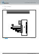
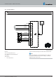
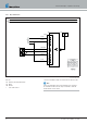
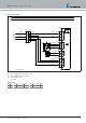
5.4.1 Easy Start Pro
0,5 GYBK
321
12
34
-XS2
-XS1
X:58
Light (+)
X:15
Ign (+)
1
2
3
-XS2
1
2
3
4
-XS1
-E1
0,22 GY
c
Θ
-B1
2
3
-XB2
0,22 BNWH0,22 BNWH
0,22 GY
0,35* RD
0,22 BURD
0,35* BN
0,22* BUBK
1
0,22 GYBK
22 1000 34 97 22
Parts list
-B1 Room temperature sensor
-E1 Easy Start Pro
c to the heater cable harness
Connectors and bush housings are shown from the cable inlet side.
Note
Further circuit diagrams for the Easy Start Pro are printed in the
Installation Instructions Plus; these are available to view and
download from the Service Portal.
34 25.2933.90.0001.0A EN | 06.2018
Technical Description | Hydronic S3 Economy