
Product Manual


For operating details and error list, refer to the “Troubleshooting
and Repair Instructions” of the heater and/or the “PLUS–Easy
Start / Altitude Kit Installation Instructions, Special Functions and
Diagnosis”.
Emergency stop – EMERGENCY OFF
If an emergency stop – EMERGENCY OFF – is necessary
during operation, please complete the following steps:
Switch the heater off at the control unit or
remove the fuse or
disconnect the heater from the battery.
5 Electrics
5.1 Heater wiring
Warning!
Safety instructions for wiring the heater!
Connect the heater electrically according to the EMC directives.
EMC can be affected in case of interventions not carried out
properly. For this reason, comply with the following instructions:
Æ
Ensure that the insulation of electrical cables is not damaged.
Æ
Avoid: Chafing, kinking, jamming or exposure to heat.
Æ Seal any connector chambers of watertight connectors not in use
with filler plugs to ensure they are dirt-proof and watertight.
Æ Electrical connections and ground connections must be free from
corrosion and securely connected.
Æ Lubricate connections and ground connections outside the heater
interior with contact grease.
Note
Position electric cables and components in the vehicle so that they
can function perfectly under normal operating conditions without
impairment (e.g. due to heat exposure, moisture, etc.).
Keep to the specified cable lengths and cable cross-sections of the
positive cable 4
2
and the negative cable 2.5
2
between the battery
and the heater. This ensures that the maximum allowable voltage
drop in the cables does not exceed 0.5V for 12V rated voltage.
If the cable (positive cable + negative cable) is lengthened up to
6m, the next-higher cable cross-section must be selected.
If the positive cable is to be connected to the fuse box (e.g.
terminal 30), the vehicle's cable from the battery to the fuse box
must also be included in the calculation for the total cable length
and re-dimensioned if necessary.
Insulate unused cable ends.
The 12 volt relay (-K1, from terminal 30 to terminal 87a) has a
maximum current carrying capacity of 40A; i.e. the value of the
vehicle's own fan fuse may not be more than 40A. Circuit diagram
see page 32.
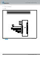
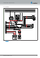
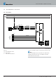
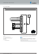
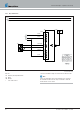
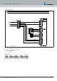
5.2 Parts list for circuit diagram for heater and cable
harness, normal and ADR version
-A10 Hydronic S3 Economy 12V control box
-A30 Fuse holder 3-pin
-B5 Flame sensor
-B10 WAF
-B11 WEF
-F1 Fuse, heater
-F2 Fuse, control unit
-F3 Fan relay fuse
-K1 Fan relay
-M3 Burner motor
-W1 Cable loom, water pump
-W2 Cable loom, metering pump
-M10 Water pump
-R1 Terminating resistor I
-R2 Terminating resistor II
-R3 Terminating resistor, stub line
-X1 Ring terminal end
-XB1 Bush housing, heater power supply
-XB2 Bush housing, heater signals
-XB3 Bush housing, heater water pump
-XB6/1 EasyScan bush housing
-XB6/3 EasyFan bush housing
-XB6/4 Bush housing, control unit
-XB7 Relay block
-XB8/1 Bush housing, metering pump plug-in connection
-XB8/2 Bush housing, water pump
-XS6/1 Mating connector with terminating resistor
-XS8 Connector housing, metering pump plug-in connection
-Y1 Fuel metering pump
a to the heater
b Activation, vehicle fan
c to the control unit
x insulate and tie back any cables that are not needed
Cable colours
RD red GR grey BK black
BU blue YE yellow GN green
WH white VT violet BN brown
25.2933.90.0001.0A EN | 06.2018 31
Technical Description | Hydronic S3 Economy