
Product Manual
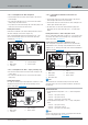
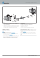
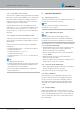

3.13.4 Installation position of the T-piece
Keep to the installation positions shown when inserting a T-piece,
see Picture 22.
Picture 22
1 Direction of flow – to the fuel tank
2 Direction of flow – from the vehicle engine
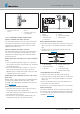
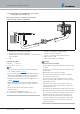
3.14 Installing the metering pump
Note
Metering pump installation instructions!
Always install the metering pump with the delivery side rising
upwards – minimum angle 15°.
Do not install the metering pump and filter near silencers and
exhaust pipes and therefore protect against unacceptable heating
(petrol max. 20 °C, diesel max. 50 °C).
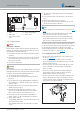
Always install the metering pump with the delivery side rising
upwards. Any installation position between 15° and 90° is allowed.
Preferred installation position: between 15° and 35°,
see Picture 21.
Picture 23
1 Installation position between 0° – 15° is not allowed
2 Preferred installation position within the range 15° – 35°
3 Installation position within the range 35° to 90° is allowed
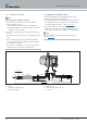
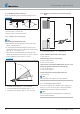
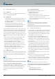
3.14.1 Allowable suction and pressure head of the metering
pump
1
3
a
c
b
2
Picture 24
1 Connection at the heater
2 max. fuel level
3 min. fuel level
Pressure head from vehicle tank to metering pump:
a = max. 3000mm
Suction head in pressure-less vehicle tank:
b = max. 500mm for petrol
b = max. 1000mm for diesel
Suction head in a vehicle tank in which negative pressure occurs
during extraction (valve with 0.03 bar in the tank cap):
b = max. 150mm for petrol
b = max. 400mm for diesel
Pressure head from the metering pump to the heater:
c = max. 2000mm
Note
After mounting the metering pump, check tank ventilation.
3.15 Fuel quality for petrol heaters
The heater runs problem-free on standard commercial quality fuel,
which you use to run your vehicle engine. Commercially available,
maximum blending of ethanol to DIN 51600 and EN 228.
Note
The heaters B 4 E and B 5 E are not approved for operation with
ethanol fuel E85 to DIN 15293.
28 25.2933.90.0001.0A EN | 06.2018
Technical Description | Hydronic S3 Economy