
Product Manual
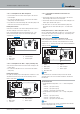
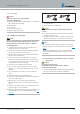

Picture 13
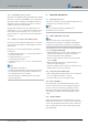
1 Connection socket to the
heater
2 Connection socket to the
T-piece
3 Connection socket to the
non-return valve
3.10.4 Coolant liquid circuit with combination valve
Using the combination valve with 5 connections
If the water flow line and water return line from the vehicle engine
to the vehicle's heat exchanger are laid separately in the engine
compartment, the combination valve with 5 connections and an
additional T-piece must be used.
Using the combination valve with 6 connections
If the water flow line and water return line from the vehicle engine
to the vehicle's heat exchanger are laid in parallel in the engine
compartment, the combination valve with 6 connections (without
T-piece) must be used.
Heating characteristic in pre-heater mode – small cooling water
circuit
Up to a cooling water temperature of approx. 67°C, the heater's
heat is fed first to the vehicle's heat exchanger only – fast heating
of the inside of the vehicle.
From a cooling water temperature of approx. 67°C, part of the
heater's heat is passed to the vehicle's engine. This causes
additional engine pre-heating, without rapid cooling of the “small
cooling water circuit” for interior heating.
Heating characteristic in auxiliary heater mode – large cooling
water circuit
While the vehicle's engine is running the heat is distributed between
the vehicle's heat exchanger and the vehicle engine – further
shortening of the heating up phase and heating of the inside of the
vehicle,
see Picture 14.
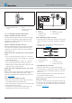
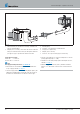
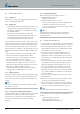
Install combination valve with 5 connections
Cut the water flow hose from the vehicle engine to the vehicle's
heat exchanger and insert the combination valve.
Cut the water return hose from the vehicle's heat exchanger to the
vehicle engine and insert the T-piece.
Use water hoses to connect the heater and water pump to the
combination valve and T-piece (as shown in the sketch).
Picture 14
1 Heater
2 Water pump
3 combination valve
(5 connections)
4 T-piece
5 Vehicle heat exchanger
6 Vehicle engine
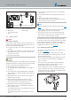
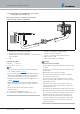
Install combination valve with 6 connections
Cut the water flow hose and the water return hose from the vehicle
engine to the vehicle's heat exchanger and insert the combination
valve.
Use water hoses to connect the heater and water pump to the
combination valve,
see Picture 15.
4
5
3
6
1 2
Picture 15
1 To the water pump
2 From the water pump
3 To the heater
4 From the vehicle's heat
exchanger
5 To the vehicle engine
6 From the vehicle engine
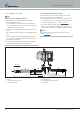
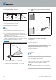
Coolant liquid with 2 non-return valves
Preheat the vehicle interior only (vehicle engine uncoupled)
Cut the water flow hose and the water return hose from the vehicle
engine to the vehicle's heat exchanger and insert one non-return
valve in each.
Insert the heater between the non-return valve and the vehicle's
heat exchanger in the water flow hose.
Use water hoses to connect the water pump to the non-return valves.
Heating characteristics
If the heater is switched on, the heat is only fed to the vehicle's own
heat exchanger. If the coolant liquid temperature has reached approx.
30°C, the vehicle fan starts and the heat is routed to the passenger
compartment,
see Picture 16.
22 25.2933.90.0001.0A EN | 06.2018
Technical Description | Hydronic S3 Economy