
Product Manual
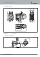

3.9.1 Installation steps
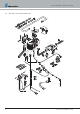
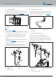
Insert the O-rings (5) in the groove of the socket.
Insert connection sockets (3 or 4) in the recesses of the sensor
cover (2). The collar of the support is above the cover.
Position the connection socket with teething in the sensor cover.
Place the sensor cover with positioned socket on the heater.
Push the connection socket completely into the connection holes in
the heat exchanger.
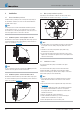
Adjust the direction for the angled connection sockets:
Lift the sensor cover up to the collar of the connection sockets
Turn connection socket in the required direction
Push sensor cover downwards and adjust the connection socket
position until the teething intermesh once again
Use screw M5 x 18 to fix the sensor cover (tightening torque
6.5+0.5 Nm).
Note
A thread-forming screw is used to fix the sensor cover. It is not
necessary to pre-cut a thread. The thread is formed by the screw on
screwing it into the tapping hole.
3.9.2 Installation instructions
Position screw by hand and screw in.
– Always keep to the given tightening torque.
When screwing for the second time also position by hand, do not
cut a new thread.
The screw is suitable for max. 6 installation attempts.
In case of repair (removal of heater) a metric screw (M5 x 18) can
be used as an alternative.
3.10 Connection to the coolant liquid circuit
Warning!
Risk of injury, scalding and burns
The high temperatures of the coolant liquid and the coolant liquid
circuit components can cause injuries, scalds and burns.
Æ Before working on the coolant liquid circuit, wait until all
components have cooled, wear safety gloves if necessary.
Æ Lay and fix parts carrying coolant liquid in such a way that they
pose no temperature risk to man, animals or material sensitive to
temperature due to radiation / direct contact.
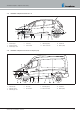
The heater is integrated in the coolant liquid circuit in the water flow
hose from the vehicle engine to the heat exchanger. There are various
installation options for this. These are described
from page 20.
Note
When installing the heater, note the flow direction of the coolant
liquid in the circuit.
Fill the heater and water hose with coolant liquid before
connecting to the coolant liquid circuit.
Lay the water hoses without any kinks, and as far as possible in a
rising position.
When laying the water hoses, maintain sufficient distance from hot
vehicle parts and sharp edges.
Protect all water hoses / water pipes from chafing and from
extreme temperatures.
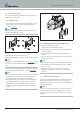
Connection of the water pump to the water socket of the heater:
Use enclosed hose and spring band clamps. Clamping range 26
– 28mm. For direct connection of the vehicle’s own water hose
to the water pump or water socket: Check the diameter and use
screw clamps if necessary
Use screw clamps to secure other hose connections (Tightening
torque: 3
+0.5
Nm).
After the vehicle has been operating for 2 hours or travelled
100km, retighten the screw clamps.
The minimum water flow rate is ensured if, at cooling water
temperature > 60°C, the temperature difference in the heating
medium between the water inlet and water outlet does not exceed
10K.
Only overpressure valves with an opening pressure of min.
0.4 – max. 2 bar may be used in the coolant liquid circuit.
The coolant liquid circuit must contain at least 10% antifreeze all
year round as corrosion protection.
During cold periods the coolant liquid circuit must contain
sufficient antifreeze. Follow the vehicle manufacturer's instructions
regarding the mix ratio.
Before initial commissioning of the heater or after changing the
coolant liquid, the entire coolant liquid circuit including heater
must be vented free of bubbles according to the instructions
issued by the vehicle manufacturer.
Only use the anti-freeze approved by the vehicle manufacturer in
the allowable mix ratio (anti-freeze / water).
Fix water hoses / water pipes securely to prevent damage and / or
odour emissions due to vibrations.
Recommendation: Fix outgoing water hoses / water pipes from the
heater at a distance of approx. 20cm using hose clips, pipe clips
or cable ties.
20 25.2933.90.0001.0A EN | 06.2018
Technical Description | Hydronic S3 Economy