
Product Manual
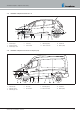

3.6 Fix the nameplate
The nameplate (1) is fastened to the side of the heater. The second
nameplate (duplicate) is enclosed with the heater and must be glued
on in a clearly visible position in the vehicle,
see Picture 6.
1
Picture 6
1 Nameplate
Note
Follow the regulations
on page 9.
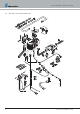
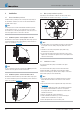
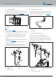
3.7 Fix the fuse holder and diagnostics connector
Use screw M6 to fix the combination bracket (1) in a suitable,
easily accessed position in the engine compartment of fix on a
stud bolt.
Clip the diagnostics connector holder (2) into the elongated hole of
the plastic bottle,
see Picture 7
Push the diagnostics connector (3) into the bracket retainer until it
audibly latches into position.
Use 2 split rivets (5) to fix the fuse holder (4). To do this, press in
both bolts until the holder sits securely on the plastic bottle.
1
2
3
4
5
5
Picture 7
1 Combined bracket
2 Retainer clip
3 Diagnostics connector
4 Fuse bracket
5 Split rivet
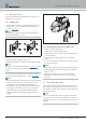
3.8 Fixing the fan relay block
Use cable tape or split rivet (2) to fix the fan relay block (1) in a
suitable accessible place. To do this, press in the bolt of the split
rivet 5.5x12, until the relay block sits securely,
see Picture 8.
Place the cover (3) on the relay block.
1
2
3
Picture 8
1 Fan relay block
2 Split rivet
3 Relay block cover
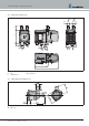
3.9 Mounting the water socket
Heater scope of supply: two straight water sockets
Installation kit scope of supply: two angled water sockets
Depending on the installation conditions, mount the straight water
connection sockets (3) or the angled water connection sockets (4)
together with the sensor cover,
see Picture 9.
Picture 9
1 Screw M5x18
2 Sensor cover
3 Connection socket, straight
4 Connection socket, angled
5 O-ring
25.2933.90.0001.0A EN | 06.2018 19
Technical Description | Hydronic S3 Economy