
Product Manual

3 Installation
3.1 Heater installation positions
Install the heater preferably in the normal position. Depending on
the installation conditions, the heater can be installed within the
allowable swivel ranges.
Note
In heating mode, the normal and maximum installation positions
shown can differ by up to +15° in all directions for a short time.
These differences, caused by tilted positions of the vehicle, do not
have any negative effects on the heater's function.
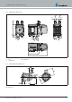
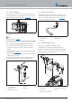
3.1.1 Installation position – heater upright / on its side
Allowable: The normal position (upright) with swivel range up to the
horizontal installation position. All installation positions between 0°
and 90° are permitted,
see Picture 1.
A
A
Picture 1
Note
In case of deviations from the normal position, always position the
exhaust connection (A) of the heater at the bottom.
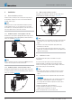
3.1.2 Installation position – heater horizontal / vertical
Allowable: Horizontal installation position with swivel range up into
the vertical installation position. All installation positions between 0°
and 90° are permitted,
see Picture 2.
Picture 2
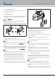
3.2 Water pump installation position
Depending on the installation conditions, the water pump can be
installed within the allowable swivel ranges,
see Picture 3.
Picture 3
Note
The water pump is not self-priming. The water inlet must therefore
be arranged so that it is always completely filled with coolant
liquid.
Installation of the water pump with the pump head facing
downwards is not allowed.
Do not mount the water pump at the lowest point of the coolant
liquid circuit, as otherwise the particles in the coolant liquid circuit
settle in the water pump.
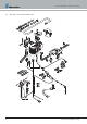
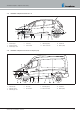
3.3 Installation location
The heater and the water pump are installed in the engine
compartment.
The heater and the water pump must be mounted below the
minimum allowable coolant liquid level (header tank, radiator,
vehicle's heat exchanger) so that the heat exchanger of the heater
and the water pump can vent automatically.
Note
In a truck the water heater is preferably fixed onto the chassis
beam underneath the driver's cab in the area of the vehicle's
engine.
Note and follow the relevant regulations and safety instructions
from page 15.
The installation suggestions made in the installation instructions
are examples. Other installation locations are acceptable if
they comply with the installation requirements stated in these
installation instructions.
Note the operating and storage temperatures.
Further installation information (e.g. for boats and ships) is
available from the manufacturer on request.
Ensure adequate distance from hot vehicle parts.
16 25.2933.90.0001.0A EN | 06.2018
Technical Description | Hydronic S3 Economy