
Corporation Computer Hardware User Manual

Prometheus CPU User Manual V1.44 Page 56
17. GENERATING AN ANALOG OUTPUT
This chapter describes the steps involved in generating an analog output (also called performing
a D/A conversion) on a selected output channel using direct programming (not with the driver
software).
There are three steps involved in performing a D/A conversion:
1. Compute the D/A code for the desired output voltage
2. Write the value to the selected output channel
3. Wait for the D/A to update
17.1 Compute the D/A code for the desired output voltage
Use the formulas on the preceding page to compute the D/A code required to generate the
desired voltage.
⇒ Note: The DAC cannot generate the actual full-scale reference voltage; to do so would require
an output code of 4096, which is not possible with a 12-bit number. The maximum output value is
4095. Therefore the maximum possible output voltage is always 1 LSB less than the full-scale
reference voltage.
17.2 Write the value to the selected output channel
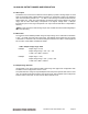
First use the following formulas to compute the LSB and MSB values:
LSB = D/A Code & 255 ;keep only the low 8 bits
MSB = int(D/A code / 256) ;strip off low 8 bits, keep 4 high bits
Example:
Output code = 1776
LSB = 1776 & 255 = 240 (F0 Hex); MSB = int(1776 / 256) = int(6.9375) = 6
The LSB is an 8-bit number in the range 0-255. The MSB is a 4-bit number in the range 0-15.
The MSB is always rounded DOWN. The truncated portion is accounted for by the LSB.
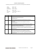
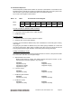
Now write these values to the selected channel. The LSB is written to Base + 6. The MSB and
channel number are written to Base + 7. The 2-bit channel no. (0-3) is written to bits 7 and 6, and
the MSB is written to bits 3-0.
outp(Base + 6, LSB);
outp(Base + 7, MSB + channel << 6);
17.3 Wait for the D/A to update
Writing the MSB and channel number to Base + 7 starts the D/A update process for the selected
channel. The update process requires approximately 30 microseconds to transmit the data
serially to the D/A chip and then update the D/A circuit in the chip. During this period, no attempt
should be made to write to any other channel in the D/A through addresses Base + 6 or Base + 7.
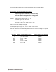
The status bit DACBUSY (Base + 3 bit 4) indicates whether the D/A is busy updating (1) or idle
(0). After writing too the D/A, monitor this bit until it is zero before proceeding to the next D/A
operation.