
Corporation Computer Hardware User Manual

Prometheus CPU User Manual V1.44 Page 40
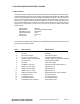
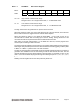
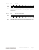
Base + 7 Write DAC MSB + Channel No.
Bit No. 7 6 5 4 3 2 1 0
Name DACH1 DACH0 X X DA11 DA10 DA9 DA8
DACH1–0 D/A channel. The value written to Base + 6 and Base + 7 are written to the selected
channel, and that channel is updated immediately. The update takes approximately
20 microseconds due to the DAC serial interface.
DA11–8 D/A bits 11 - 8; DA11 is the MSB. D/A data is an unsigned 12-bit value.
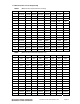
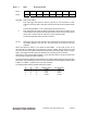
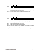
Base + 7 Read Analog Operation Status
Bit No. 7 6 5 4 3 2 1 0
Name DMAINT TINT DINT AINT ADCH3 ADCH2 ADCH1 ADCH0
DMAINT DMA interrupt status. 1 = interrupt pending, 0 = interrupt not pending.
TINT Timer interrupt status, same values as above.
DINT Digital I/O interrupt status, same values as above.
AINT Analog input interrupt status, same values as above.
ADCH3-0 Current A/D channel. This is the channel that will be sampled on the next
conversion.
When any of bits 7–4 are 1, the corresponding circuit is requesting service. The interrupt routine
must poll these bits to determine which circuit needs service and then act accordingly.