
Corporation Computer Hardware User Manual

Prometheus-LC CPU User Manual V1.0 Page 29
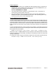
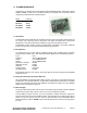
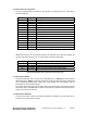
12.2 Panel Board I/O Connectors
The I/O connectors below are located on the top side of the board and are for connection to
external equipment.
Location Type Description
J2 DB-9M Serial port COM1
J4 DB-9M Serial port COM2
J6 DB-9M Serial port COM3
J7 DB-9M Serial port COM4
J10 DB-25F Parallel port LPT1
J11 2.5mm +5VDC input power (tip = +, ring = -)
J13 DB-9M Multi I/O power connector
J14 MD-6 PS/2 mouse connector
J15 MD-6 PS/2 keyboard connector
J18 RJ-45 Ethernet connector (not present)
J21 IDC-50 Data acquisition connector (not present)
J22 USB A USB connector
J23 USB A USB connector
J27 DB-15F Video (VGA) connector (passthrough for add-on board)
Panel Board Top Side / External Use I/O Connectors
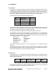
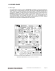
Additional connectors are on the bottom side and are intended for use with other boards and
circuitry inside the enclosure, such as a video board or DC/DC power supply.
Location Type Description
J3 Pin header Speaker and miscellaneous functions
J5 Pin header Power connection to DC/DC power supply input
J12 Pin header Power connection to/from DC/DC power supply
J25 Pin header Pass-through connector for VGA board
Panel Board Bottom Side / Internal Use I/O Connectors
12.3 Panel Board Cables
The panel board ships with a 10-wire video cable (DSC part no. 698010) and a 2-wire power
cable (DSC part no. 698011). These are intended for use with the optional accessory video board
and a Jupiter-MM (JMM) power supply when these boards are used together with the
Prometheus-LC CPU and panel board.
The 10-wire video cable connects the VGA output of the video board to pin header J25 on the
panel board. J25 is compatible with a number of companies’ PC/104 video boards that provide a
10-pin connector for the video out.
12.4 Panel Board Hardware
The panel board also comes with mounting hardware for installing it and the CPU into an
enclosure such as the Pandora system.