
Corporation Computer Hardware User Manual

6. SYSTEM I/O
6.1 Serial Port Connectors
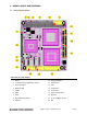
Morpheus supports serial protocols RS-232, RS-422, and RS-485. Serial port 1 supports RS-232 only
and serial port 2 supports RS-232/422/485. J5 configures the serial protocol for port 2. Information
concerning J5 can be found on page 7. When connecting cables, connect the side with the red stripe to
pin 1 on the Morpheus. Using the cable supplied in the cable kit C-MOR-KIT, the DB-9 connector will
provide the standard DTE pinout for a PC serial port. The pinouts shown below are for the pin headers on
Morpheus, NOT the DB-9 connector.
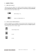
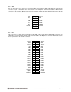
RS-232 Configuration:
DCD
1 2 RXD
TXD 3 4 DTR
GND 5 6 DSR
RTS 7 8 CTS
RI 9 10 NC
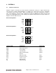
RS-485 Configuration:
DATA+
1 2 DATA-
NC 3 4 NC
GND 5 6 NC
NC 7 8 NC
NC 9 10 NC
RS-422 Configuration:
TXD+
1 2 TXD-
NC 3 4 NC
GND 5 6 NC
NC 7 8 RXD+
RXD- 9 10 NC
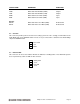
SIGNAL NAME DEFINITION DIRECTION
RS-232:
DCD Data Carrier Detect Input
RXD Receive Data Input
TXD Transmit Data Output
DTR Data Terminal Ready Output
GND Ground ---
DSR Data Set Ready Input
RTS Request To Send Output
CTS Clear To Send Input
RI Ring Indicator Input
NC Not Connected ---
Morpheus CPU User Manual V1.01 Page 8