HYDRAULIC POWER UNIT PARTS LIST & OPERATOR’S MANUAL MODEL CB15E XL December 2013 Part #1801653
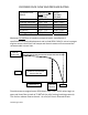
CB POWER PACK FLOW AND PRESSURE RATING CB POWER PACK MODEL 15 Electric 18 Briggs Vanguard 20 Electric 21 Honda 30 Electric 35 Briggs Vanguard MAXIMUM NO LOAD FLOW GPM/LPM 12.75 / 48.2 11.6 / 43.9 14.9 / 56.4 14.1 / 53.2 20.4 / 77.2 17.2 / 65.1 RELIEF SETTING PSI/BAR 2100 / 145 2850 / 196.5 2400 / 165.5 2600 / 179.3 2300 / 158.6 3000 / 206.9 Maximum no load flow is based on pump and motor manufacturer’s specifications for pump displacement and no load RPM.
Table of Contents Description Page No. 1. 208/230/460 Volt Hydraulic Power Supply ...........................................4 2. 575 Volt Hydraulic Power Supply .........................................................8 3. Hydraulic Schematic .............................................................................12 4. Hose Kit ..................................................................................................13 5. Hydraulic Tank Assembly ..............................................
646206 CB15 HYDRAULIC POWER SUPPLY, 208 - 460 VOLT 42 41 5 1 7 13 DETAIL A SCALE 1 : 4 4X 16 14 15 35 4X 3 36 17 31 DETAIL C SCALE 1 : 2 8 4X 21 20 22 19 2 26 18 DETAIL B SCALE 1 : 3 4 2X 24 23
4646206 CB15 HYDRAULIC POWER SUPPLY, 208 - 460 VOLT ITEM 1 PART NO. 4646156 QTY. 1 DESCRIPTION CB-XL Frame Assembly 2 2400643 2 Wheel, 12 x 2-5/8 x 3/4" 3 4 2400615 2501767 2 2 Set Collar, 3/4" Rubber Bumper 5 6 2900022 2900508 16 2 Flat Washer, 5/16" SAE Cap Screw, Hex Hd., 5/16-18 x 1-1/2" 7 2900039 8 Lock Nut, 5/16-18 Nylon 8 9 4600079 2800083 1 9 Electric Motor, 15 HP, 3 Ph., 230/460 V.
4646206 CB15 HYDRAULIC POWER SUPPLY 208 - 460 VOLT 1 40 39 TO EACH WIRE IN THE MOTOR WIRE BOX.
4646206 CB15 HYDRAULIC POWER SUPPLY, 208 - 460 VOLT ITEM 1 PART NO. 4646156 QTY. 1 DESCRIPTION CB-XL Frame Assembly 2 2400643 2 Wheel, 12 x 2-5/8 x 3/4" 3 4 2400615 2501767 2 2 Set Collar, 3/4" Rubber Bumper 5 6 2900022 2900508 16 2 Flat Washer, 5/16" SAE Cap Screw, Hex Hd., 5/16-18 x 1-1/2" 7 2900039 8 Lock Nut, 5/16-18 Nylon 8 9 4600079 2800083 1 9 Electric Motor, 15 HP, 3 Ph., 230/460 V.
4640037 CB15 HYDRAULIC POWER SUPPLY, 575 VOLT 42 41 5 1 7 13 DETAIL A SCALE 1 : 4 4X 16 14 15 35 4X 3 31 36 17 DETAIL C SCALE 1 : 2 8 4X 22 21 20 19 2 26 18 DETAIL B SCALE 1 : 3 8 2X 24 23
4640037 CB15 HYDRAULIC POWER SUPPLY, 575 VOLT ITEM 1 PART NO. 4646156 QTY. 1 DESCRIPTION CB-XL Frame Assembly 2 2400643 2 Wheel, 12 x 2-5/8 x 3/4" 3 4 2400615 2501767 2 2 Set Collar, 3/4" Rubber Bumper 5 6 2900022 2900508 16 2 Flat Washer, 5/16" SAE Cap Screw, Hex Hd., 5/16-18 x 1-1/2" 7 2900039 8 Lock Nut, 5/16-18 Nylon 8 9 4600080 2800083 1 9 Electric Motor, 15HP, 3 PH., 575V.
4640037 CB15 HYDRAULIC POWER SUPPLY, 575 VOLT 1 10 TO EACH WIRE IN THE MOTOR WIRE BOX.
4640037 CB15 HYDRAULIC POWER SUPPLY, 575 VOLT ITEM 1 PART NO. 4646156 QTY. 1 DESCRIPTION CB-XL Frame Assembly 2 2400643 2 Wheel, 12 x 2-5/8 x 3/4" 3 4 2400615 2501767 2 2 Set Collar, 3/4" Rubber Bumper 5 6 2900022 2900508 16 2 Flat Washer, 5/16" SAE Cap Screw, Hex Hd., 5/16-18 x 1-1/2" 7 2900039 8 Lock Nut, 5/16-18 Nylon 8 9 4600080 2800083 1 9 Electric Motor, 15HP, 3 PH., 575V.
GAGE HOSE 4646055 ALL HOSES ARE IN KIT 4646143 PRESSURE PORTS HOSE 4646056 90 END TO VALVE CF TANK IN HOSE 4699980 ELECTRIC HOSE 4646085 ELECTRIC EX FILTER COOLER CB15 XL HYDRAULIC SCHEMATIC HOSE 4646086 HOSE 4646086 RETURN PORTS HOSE 4646056 90 END TO MANIFOLD
4646143 CB15XL HOSE KIT 22.0 1 28.8 2 19.25 3 23.6 4 16.6 5 ITEM 1 2 3 4 5 PART NO. QTY. 4699980 1 3202317 2 3200135 2 4646085 1 3200290 2 4646056 2 3200290 1 3200408 1 4646086 2 3201989 2 3200135 2 4646055 1 3200128 1 3200145 1 3201110 1 DESCRIPTION Hose Assembly, 1 x 22" Fitting, 1" FJIC to 1" Hose Barb Hose Clamp #16 Hose Assembly, 1/2"X 28-3/4" Fitting, 1/2" Female JIC to 1/2" Hose Crimp Hose Assembly, 1/2" X 19-1/4" Fitting, 1/2" Female JIC to 1/2" Hose Crimp Elbow, 1/2" F.
4646173 HYDRAULIC TANK ASSEMBLY 18 24 23 17 22 16 12 15 14 9 6 8 11 19 13 20 21 10 4 2 2 1 3 7 5 14 3
4646173 HYDRAULIC TANK ASSEMBLY ITEM 1 PART NO. 4640120 QTY. 1 DESCRIPTION Hydraulic Tank Weldment 2 3 3200409 3200427 2 2 Street Elbow, 1" NPT Nipple, 1" NPT x 4", Schedule 40 4 3200289 1 Elbow, 1" M. Pipe to 1" M.
4646174 CB15 XL PANEL ASSEMBLY 30 7 31 33 32 34 40 38 6X 2 3 4 7 8 39 17 41 19 20 35 26 2 23 21 1 35 24 22 18 36 37 3X 29 28 12 13 5 27 15 11 14 25 27 9 7 10 16 16 10
4646174 CB15 XL PANEL ASSEMBLY ITEM PART NO. QTY. DESCRIPTION 1 4646141 1 Instrument Panel 2 3 2900022 2900031 8 6 Flat Washer, 5/16" SAE Lock Washer, 5/16" Split 4 2900138 6 Cap Screw, Hex Hd., 5/16-18 x 1" 5 4646102 1 Manifold, SAE O-Ring 6 4646101 1 Manifold, 3/4 NPT 7 8 2900009 2901001 20 8 Flat Washer, 1/4" SAE Cap Screw, Hex Hd.
4646032 STARTER BOX ASSEMBLY 208 - 460 VOLT ROUTE INTO STARTER BOX TO CUSTOMER SUPPLIED CONNECTOR & CORD. B 9 DETAIL B SCALE 1 : 3 3 1 2 4 TO MOTOR A 6 DETAIL A SCALE 1 : 2 7 8 5 18 ITEM PART NO. QTY. DESCRIPTION 1 2 4600276 2800898 1 1 Starter Box, 230-460V Connector, 1", Sealtite, 90 Deg. 3 2800193 1 Lock Nut, 1" 4 5 4646144 4646145 1 1 Conduit, Seal Tite, 1" x 29" Wire Assy., 6 Gage, Green, 50" 6 4646146 3 Wire Assy., 8 Gage, Black, 55" 7 4600165 1 Wire Assy.
4646032 STARTER BOX ASSEMBLY 208 - 460 VOLT SEE ALSO SCHEMATIC ON MOTOR NAME PLATE.
Intentionally Blank 20
4600276 STARTER BOX 230 - 460 VOLT 12 13 11 15 18 17 11 14 6 7 5 6 3 10 4 9 7 8 2 1 16 ITEM PART NO. QTY. DESCRIPTION Electrical Box Base 1 6040300G 1 2 6040598 1 Sub-plate Machine Screw, Pan Hd., M4-0.7 x 3 2900676 4 8mm 4 2801704 1 Contactor, 220-240V (includes coil) 2801265 1 Replacement Coil, 220-240V 5 2800899 1 Overload Relay, 13-52 Amp 6 2901827 6 Cap Screw, Soc. Hd., #8-32 x 5/8" 7 2901437 6 Flat Washer, #10 8 2800315 2 Grounding Lug 9 2900024 1 Lock Washer, 1/4" Split ITEM PART NO. QTY.
4646074 STARTER BOX ASSEMBLY, 550-600 VOLT TO STARTER BOX OVERLOAD RELAY AND GROUND LUG TO CUSTOMER SUPPLIED CONNECTOR & CORD. B 3 DETAIL B SCALE 1 : 4 7 9 2 8 1 4 3X 4646146 BLACK TO MOTOR A 4646145 GREEN TO GROUND LUG ITEM PART NO. 6 DETAIL A SCALE 1 : 2 5 22 QTY. DESCRIPTION 1 2 4600274 2800898 1 1 Starter Box, 550-600 Volt Connector, 1", Sealtite, 90 Deg. 3 2800193 1 Lock Nut, 1" 4 5 4646144 4646145 1 1 Conduit, Seal Tite, 1" x 29" Wire Assy.
4600274 STARTER BOX, 550-600 VOLT 1 REPLACE BASE WITH 6040300G AND INSERTS 2 3 ITEM PART NO. QTY.
2801033 STARTER BOX, 550-600 VOLT 12 13 15 14 12 5 13 4 6 8 11 7 4 10 9 3 2 1 16 18 17 19 20 21 24
2801033 STARTER BOX, 550-600 VOLT 12 4600295 13 SET TO MOTOR AMP RATING 4600298 4600297 5 TRIP CLASS - 10 RESET - A PHASE - OFF 4 4600294 4600293 N.O. ONLY ITEM 1 2 3 4 PART QTY. DESCRIPTION NO. 2702419 1 Electrical Box (Base) 6040598 1 Sub-plate Machine Screw, Pan Hd., M4-0.
NOTES ____________________________________________________ ____________________________________________________ ____________________________________________________ ____________________________________________________ ____________________________________________________ ____________________________________________________ ____________________________________________________ ____________________________________________________ ____________________________________________________ _____________________________
RELIEF CARTRIDGE WATER CONNECTIONS FLOW CONTROL QUICK DISCONNECTS 27
GENERAL SAFETY PRECAUTIONS WARNING: Do not operate power unit without reading this entire manual and the engine operation manual first. Keep manuals with power unit at all times for reference. This manual describes the operating procedures, care, maintenance, adjustments, and safety precautions for proper use of this machine. This equipment is intended for industrial applications by experienced operators.
Do not operate the power unit if a gasoline odor is present. Do not use flammable solvents around the power unit motor. Do not operate the power unit within 3 ft. (1 meter) of buildings or flammable objects. Allow the motor to cool before storing the unit in an enclosed area. To avoid personal injury or equipment damage, all tool repair, maintenance and service must only be performed by authorized and properly trained personnel.
DESCRIPTION AND SPECIFICATIONS Pump: Gear, pump rotation is clockwise (motor is CCW). Maximum GPM: 12-3/4 GPM (48.2L/M). Flow will decrease as pressure increases. Hydraulic Fluid Tank Capacity: 11 gallons (41.6Liters) Hose Couplings: Bruning quick disconnect, 3/4 inch & ½ inch Relief Pressure: Factory set at 2100 PSI/145 Bar (at valve outlet port). Adjustable to 750 PSI/52 Bar, CURRENT LIMITTED TO 2100 PSI. Electric Motor: Baldor 15 HP, C Face, 3450 RPM, 208-460 Volts, 575 Volts (Canada only).
HOSES: Large diameters and short lengths are preferred and offer the highest system efficiency. If one is operating 50 ft (15.2M) from the power source, there is also a 50 ft (15.2M) return for a 100 ft (35.5M) total hose length. With 12 GPM and oil at 100 deg. F (37.8C), this could result in a 300 psi (20.6 Bar) pressure loss with ½” hose and a 100 psi (6.9 Bar) loss with 5/8” hose. Pressure loss will change dramatically with oil temperature.
Shutting Down: Shift the flow control valve to zero to unload the system. Press the stop button at the top of the starter box. OPERATING DRIVEN EQUIPMENT IMPORTANT: The quick disconnects must be clean when connecting hoses and devices. Dirty connections may result in contamination and premature failure of system or tool components. The operator must know the hydraulic requirements and limitations of the driven equipment and the appropriate adjustments must be made on the controls.
TROUBLESHOOTING PROBLEM POSSIBLE SOLUTIONS 1) Pull out stop button on starter box. 2) Confirm proper voltage. Electric motor will not start. Running with no pressure. System builds high pressure with flow control valve set to zero. The motor may be running backwards, should be counter clockwise. Reverse any two of the 3 power wires coming into the starter box. Contamination may have plugged an orifice in the CF port of the flow valve.
NOTES ____________________________________________________ ____________________________________________________ ____________________________________________________ ____________________________________________________ ____________________________________________________ ____________________________________________________ ____________________________________________________ ____________________________________________________ ____________________________________________________ _____________________________
Intentionally Blank
EQUIPMENT AND PARTS WARRANTY Diamond Products warrants all equipment manufactured by it against defects in workmanship or materials for a period of one (1) year from the date of shipment to Customer.