Dialogic® SS7G2x Signaling Server SGW Mode User Manual www.dialogic.
Copyright© 2005-2007 Dialogic Corporation. All Rights Reserved. You may not reproduce this document in whole or in part without permission in writing from Dialogic Corporation. All contents of this document are furnished for informational use only and are subject to change without notice and do not represent a commitment on the part of Dialogic Corporation or its subsidiaries (“Dialogic”). Reasonable effort is made to ensure the accuracy of the information contained in the document.
Dialogic® SS7G2x Signaling Server SGW Mode User Manual Issue 4 Contents 1 Overview .................................................................................................................. 8 1.1 General Description............................................................................................. 8 1.2 Related Information ............................................................................................ 8 1.3 Applicability ......................................................
Contents 4.14 4.13.1 Configuration Update from a Remote Data Centre .......................................26 4.13.2 Configuration Update from CD ROM...........................................................26 4.13.3 Configuration Update from Startup............................................................26 System Licenses ................................................................................................27 4.14.1 Purchasing System Licenses ...............................................
Dialogic® SS7G2x Signaling Server SGW Mode User Manual Issue 4 6.7 6.8 6.9 6.10 6.11 6.12 6.13 6.6.4 C7LSP – CCS SS7 Link Set Print................................................................69 6.6.5 C7RTI – CCS SS7 Route Initiate ................................................................70 6.6.6 C7RTC – CCS SS7 Route Change...............................................................71 6.6.7 C7RTE – CCS SS7 Route End ....................................................................
Contents 6.14 6.13.8 SNNAE – SIGTRAN Network Appearance End ............................................ 118 6.13.9 SNNAP – SIGTRAN Network Appearance Print ........................................... 119 6.13.10SNSLI – SIGTRAN Signaling Link Initiate .................................................. 120 6.13.11SNSLC – SIGTRAN Signaling Link Change................................................. 121 6.13.12SNSLE – SIGTRAN Signaling Link End ...................................................... 121 6.
Dialogic® SS7G2x Signaling Server SGW Mode User Manual Issue 4 9.5.7 Software Option Installation ................................................................... 157 10 SS7G2x SNMP MIB ................................................................................................. 158 11 Worked Configuration Examples ............................................................................ 160 11.1 Backhaul Configuration .........................................................................
Chapter 1 Overview Chapter 1: Overview 1.1 General Description The Dialogic® SS7G21 and SS7G22 Signaling Servers, (hereinafter sometimes referred to collectively as "the SS7G21 and SS7G22 products," individually as "SS7G21" and "SS7G22," respectively, or individually or interchangeably as "SS7G2x"), with the Dialogic® SS7SBG20SGW SGW Mode software license installed and enabled, operate as SIGTRAN Signaling Gateways (hereinafter sometimes referred to as "Signaling Gateway").
Dialogic® SS7G2x Signaling Server SGW Mode User Manual Issue 4 The latest software and documentation supporting SS7G2x products is available on the web at http://www.dialogic.com/support/helpweb/signaling. The product data sheet is available at http://www.dialogic.com/support/helpweb/signaling. For more information on Dialogic® SS7 products and solutions, visit http://www.dialogic.com/support/helpweb/signaling.
Chapter 1 Overview The Signaling Gateway provides SNMP V1 support to allow the reporting of alarms to an SNMP manager. See Chapter 10, “SS7G2x SNMP MIB” for more information. The Signaling Gateway has alarm indicators on the front panel and alarm relays for connection to an integrated management system. 1.7 Configuration and Program Storage All configuration data is stored on hard disk and is automatically recovered after system restart.
Dialogic® SS7G2x Signaling Server SGW Mode User Manual Issue 4 The Signaling Gateway supports up to 128 TDM SS7 signaling links allowing the Signaling Gateway to interface over TDM to a maximum of 64 other signaling points. If required, each signaling link in a link set can be terminated on a separate signaling board providing additional resilience. The Signaling Gateway can have a presence in up to four separate IP subnets.
Chapter 1 Overview 1.9.5 Remote Data Centres The Signaling Gateway supports the transfer of software updates, configuration files, alarm reports and periodic measurements over Ethernet to/from a remote location, the Remote Data Centre (RDC). Multiple RDCs can be configured by specifying an IP address and a user name and password for the Signaling Gateway to use to “logon” to the RDC. Data transfer to the RDC uses the File Transfer Protocol (FTP).
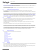
Dialogic® SS7G2x Signaling Server SGW Mode User Manual Issue 4 Figure 1. M3UA Backhaul Configuration SS7 Links M3UA Links ASP1 SEP SS7G2x Application Server (AS) ASP2 1.9.8 M2PA Longhaul Operation The Signaling Gateway is capable of replacing TDM SS7 links with signaling links operating over IP providing the equivalent functionality to MTP Layer 2 by using the SIGTRAN M2PA protocol.
Chapter 1 Overview As the Signaling Gateway supports static, rather than dynamic IP routing, the Signaling Gateway may not be configured with different IP addresses within the same IP network. Instead, resilience between two IP ports within the same network can be achieved by using IP port bonding, which allows two physical IP ports to be bonded together in an active/standby configuration under a single IP address. See Section 7.6.1, “IP Port Bonding” on page 142 for more information. 1.9.10.
Dialogic® SS7G2x Signaling Server SGW Mode User Manual Issue 4 Chapter 2: Specification 2.1 Hardware Specification Full details of the Signaling Gateway hardware specification are given in the Dialogic® SS7G21 and SS7G22 Hardware Manual. 2.2 System Capacity The maximum capacity is dependent on the number and type of signaling boards installed. The numbers given in this section are for a single unit.
Chapter 3 Installation and Initial Configuration Chapter 3: Installation and Initial Configuration 3.1 Installation Note: The Signaling Gateway should only be installed by suitably qualified service personnel. Important safety and technical details, required for installation, are given in the Dialogic® SS7G21 and SS7G22 Hardware Manual. In order to complete the installation of the Signaling Gateway unit, follow the steps below: 1. Connect a VT100 terminal to the unit (see Section 3.2). 2.
Dialogic® SS7G2x Signaling Server SGW Mode User Manual Issue 4 3. If a download is required, store the distribution file in an empty directory on the hard drive of the downloading machine. 4. Follow the steps detailed in Section 4.11, “Updating System Software” on page 24 in order to carry out the update of the system software. 3.4 Initial Configuration By default, the Signaling Gateway is shipped configured to operate in SIU mode.
Chapter 3 Installation and Initial Configuration Note: The protocol and mode parameters are only present if licensed. When a protocol or mode is active, the parameter shows the value “Y”, and when inactive, the parameter shows the value “N”. The new IP address parameters is initialized with immediate effect. If the IP address used to login to the unit for the telnet session is changed, the user is automatically logged out of the session.
Dialogic® SS7G2x Signaling Server SGW Mode User Manual Issue 4 Once activated, a future user is required to set up an SSH tunnel prior to telnet access. For a client on a Linux® or Solaris™ like operating system, login for telnet using the ssh application. The ssh application should be invoked using a shellscript of the following form: #!/bin/sh ssh -l siuftp -C -f $1 -L 2323:$1:8101 sleep 5 telnet localhost 2323 3.
Chapter 4 Operation Chapter 4: Operation 4.1 General The Signaling Gateway can be configured by the user from either serial port 2 (COM2, on the rear panel) or by using telnet over the Ethernet interface. The serial port can be configured over a range of baud rates and parity. The default configuration for the port is 9600 bits/s, 8 data bits, 1 stop bit, and no parity. Serial port 1 (COM1, on the front panel) is not supported on the SS7G2x.
Dialogic® SS7G2x Signaling Server SGW Mode User Manual Issue 4 4.3 Command Character Set and Syntax The only characters used for commands and parameters are: • The letters A to Z and a to z, referred to as . The case of characters in command names and parameter names is not significant. • • The digits 0 to 9, referred to as • The DEL (Delete) character or the BS (Backspace) character is used to delete characters on the current line.
Chapter 4 Operation To ensure correct operation of the character deletion, the maximum number of characters entered on a single command line should be no greater than the number of characters that can be displayed on a single line of the terminal (to prevent text “wrap around”). If a command is longer than one line, each line before the last should be terminated with a complete parameter value followed by a comma and CR. The command can then continue on the next line.
Dialogic® SS7G2x Signaling Server SGW Mode User Manual Issue 4 Table 1. Command Rejection Responses (Continued) Response 4.9 Reason for Rejection INVALID INFORMATION GROUPING The type of information grouping used in the input of the parameter value is not valid. INVALID INDICATOR This command contains a ‘format character’ (‘:’, ‘;’, etc.) that is not valid for this command. GENERAL ERROR Command unable to execute due to an external error (for example, a missing or write-protected CDROM).
Chapter 4 Operation 4.10 Backing Up System Software The user can backup a binary copy of the Signaling Gateway software for restoration later. 4.10.1 Software Backup to a Remote Data Centre The procedure to perform a software backup to an Remote Data Center (RDC) is as follows: 1. The user should enter: CNBUI: RDC=, DTYPE=SOFTWARE, DIRECTORY=,FILE=; to request that the software be backed up to an RDC where the software file
Dialogic® SS7G2x Signaling Server SGW Mode User Manual Issue 4 CNUPI:DTYPE=SOFTWARE,DIRECTORY=,FILE=; to request that the software be updated from CD ROM. Note: The directory and filename are optional and when not used the system looks for the file sgw.tgz in the CR ROM root directory. 3. Prompts are displayed asking first if the user is certain that they wish to upgrade the software and then to put the first software update disk in the CD ROM drive.
Chapter 4 Operation 4.13 Updating Configuration Data Valid configuration data can be stored by the Signaling Gateway at a Remote Data Center (RDC) using the CNBUI command (see Section 4.12), on CD ROM or on a remote machine accessible via FTP. This configuration data can then be restored as described in the following subsections. 4.13.1 Configuration Update from a Remote Data Centre The procedure to perform a configuration update from a Remote Data Center (RDC) is as follows: 1.
Dialogic® SS7G2x Signaling Server SGW Mode User Manual Issue 4 Software Update from Startup using a CD 1. Place the CD containing the sgw.tgz file in the CD ROM drive. 2. Restart the system. The new configuration is installed and started automatically. 4.14 System Licenses Each mode of operation (SIU, DSC or SGW) supports a number of different protocol and software options. This section describes how additional licenses are purchased and installed on a system. 4.14.
Chapter 4 Operation The Licence Activation process is web-based and the Licence File is sent by email. The user performs License Activation by visiting the web site: http://membersresource.dialogic.com/ss7/license/license.asp (or an alternative URL if listed on the Licence Certificate).
Dialogic® SS7G2x Signaling Server SGW Mode User Manual Issue 4 4.14.4 License Update by FTP The user is also able to install licenses from system start. Note: Installation of licenses from system start is not normal operating procedure and should only be used if the user is unable to install licenses via MML. The procedure to install licenses from system start is as follows: 1. Rename the purchased license file to sgw.lic. 2. Establish an FTP session (see Section 4.9, “FTP Access” on page 23). 3.
Chapter 5 Parameter Definitions Chapter 5: Parameter Definitions 5.1 Parameter Table Table 2 lists all parameters and details the possible values. All numeric parameters are entered and output in decimal notation. is either , , , $, or -. The use of quotation marks to delimit text strings is not required. Table 2.
Dialogic® SS7G2x Signaling Server SGW Mode User Manual Issue 4 Table 2. Parameter Definitions (Continued) Name Description Range DATE Calendar date, in the format: xxxx-yy-zz where: • xxxx – 4 digit year • yy – 2 digit month • zz – 2 digit day xxxx – 1990 to 2037 yy – 01 to 12 zz – 01 to 31 DBITS Number of data bits on V.24 port 7 or 8 DEST Signaling Gateway Destination Point ID 1 to 512 DIRECTORY Directory name on a remote data centre.
Chapter 5 Parameter Definitions Table 2. Parameter Definitions (Continued) Name 32 Description Range Notes FTPPWD FTP Password enabled parameter. Set to Y to enable ftp password protection, or N to disable password protection. Y or N Default = Y FTPSER Indicates whether the Signaling Gateway can act as a ftp server or not. Set to Y to enable the ftp server, or N to disable the ftp server.
Dialogic® SS7G2x Signaling Server SGW Mode User Manual Issue 4 Table 2. Parameter Definitions (Continued) Name Description Range LS1 Primary link set associated with an SS7 route 1 to 64 LS2 Secondary linkset associated with an SS7 route 1 to 64 LSSIZE Maximum number of SS7 links allowed in the link set. The link set size is used to determine the load sharing algorithm used across the link set.
Chapter 5 Parameter Definitions Table 2.
Dialogic® SS7G2x Signaling Server SGW Mode User Manual Issue 4 Table 2. Parameter Definitions (Continued) Name Description Range Notes RESTART Specifies the type of restart operation, which can be one of the following: • NORMAL - The system undergoes a full system restart, resetting the hardware, operating system and SIU software. This is the default behavior. NORMAL resets should be used for software upgrade or for maintenance events. • SOFT - The system restarts the application software.
Chapter 5 Parameter Definitions Table 2. Parameter Definitions (Continued) Name Range Notes SPEED The speed of an Ethernet port. The values 10, 100, 100 select 10 MHz, 100 MHz and 1 GHz respectively. An “H” appended to the value indicates half-duplex operation; values without the appended “H” are full-duplex operation.
Dialogic® SS7G2x Signaling Server SGW Mode User Manual Issue 4 Table 2. Parameter Definitions (Continued) Name 5.
Chapter 5 Parameter Definitions 5.3 Signaling Gateway Timers 5.3.1 Signaling Gateway-Specific Timers Table 4 shows the Signaling Gateway specific timers. Timers for specific protocols are given in subsequent tables in this section. Table 4. Signaling Gateway Specific Timers T0 5 7 5.3.2 Range (seconds) Default (seconds) Description 7 Wait for board response guard timer. This timer starts when internal messages are sent to a signaling board and stopped when an acknowledgement is received.
Dialogic® SS7G2x Signaling Server SGW Mode User Manual Issue 4 Table 6. MTP3 ANSI Timers (Continued) 5.3.3 TO Range (milliseconds) Default (milliseconds) 6 500 to 1200 1000 10 30 to 60secs 45 sec.
Chapter 6 Command Definitions Chapter 6: Command Definitions 6.1 Command Groups The commands are broken down into a number of command groups as follows: • • • • • • • • • • • 6.
Dialogic® SS7G2x Signaling Server SGW Mode User Manual Issue 4 6.
Chapter 6 Command Definitions 6.4.1 ALCLS – Alarm Class Set Synopsis This command assigns an alarm class value to a specified fault code(s). The alarm class (CLA) is used to determine whether the alarm is classed as Minor, Major or Critical and in turn governs the alarm LED, relay and SNMP alarm that are activated when the condition exists. Each alarm code (CODE) has a factory-set default class. See Chapter 8, “Alarm Fault Code Listing” for the factory default for each alarm code.
Dialogic® SS7G2x Signaling Server SGW Mode User Manual Issue 4 6.4.3 ALFCP – Alarm Fault Code Print Synopsis This command gives a printout of the alarm class of the specified fault code(s). The alarm class (CLA) is used to determine whether the alarm is classed as Minor, Major or Critical and in turn governs the alarm LED, relay and SNMP alarm that are activated when the condition exists. Each alarm code (CODE) has a factory-set default class.
Chapter 6 Command Definitions 6.4.4 ALLIP – Alarm List Print Synopsis This command gives a printout of all ACTIVE fault codes stored in the system’s alarm log. Each fault code (CODE) is associated with an alarm class (CLA) which may be Minor, Major or Critical. The alarm class in turn governs which alarm LED, relay or SNMP alarm is activated when the condition exists.
Dialogic® SS7G2x Signaling Server SGW Mode User Manual Issue 4 6.4.5 ALLOP – Alarm Log Print Synopsis This command gives a printout of the alarm log. If no code or class is entered, the whole log is output. Each fault code (CODE) is associated with an alarm class (CLA) which may be Minor, Major or Critical. The alarm class in turn governs which alarm LED, relay or SNMP alarm that is activated when the condition exists.
Chapter 6 Command Definitions 6.4.6 ALREI – Alarm Reset Initiate Synopsis This command removes alarms that have cleared from the alarm log. Attempts to remove commands that do not have the status CLEARED are rejected. If parameter ALP is omitted, all alarms with status CLEARED are removed. Syntax ALREI[:ALP=]; Prerequisites None Attributes None Examples ALREI:ALP=100; ALREI; 6.4.
Dialogic® SS7G2x Signaling Server SGW Mode User Manual Issue 4 6.4.8 ALTEE – Alarm Test End Synopsis Clears a test alarm. Syntax ALTEE; Prerequisites • The alarm test must already have been initiated.
Chapter 6 Command Definitions 6.
Dialogic® SS7G2x Signaling Server SGW Mode User Manual Issue 4 6.5.1 CNBOI – Configuration Board Initiate Synopsis This command defines a new board on the system. The user should specify the board position (BPOS) within the unit, the physical type of the board (BRDTYPE) and the signaling type (SIGTYPE), which identifies the software that will run on the board. See Section 7.1.2, “Boards and PCMs” on page 136 for a more detailed description of board configuration.
Chapter 6 Command Definitions 6.5.3 CNBOP – Configuration Board Print Synopsis This command gives a print out of all configured boards. Syntax CNBOP; Prerequisites None Attributes None Examples CNBOP; Output Format Board Configuration BPOS BRDTYPE SIGTYPE 1 SPCI2S-4-2 SS7 3 SPCI2S-4-2 SS7 EXECUTED 6.5.4 CNBUI – Configuration Back Up Initiate Synopsis This command backs up either the configuration data or the current software distribution to a Remote Data Centre (RDC).
Dialogic® SS7G2x Signaling Server SGW Mode User Manual Issue 4 6.5.5 CNMOI – Configuration Monitor Initiate Synopsis This command initiates the monitoring of an object on the Signaling Gateway. An object is currently a C7LINK. For signaling, the STS monitors information sent from the EQU of the signaling link and the RTS monitors information received by the signaling link. Syntax CNMOI:C7LINK=,STS=,RTS=; Prerequisites • • If specified, the C7LINK has already been initiated and must have a TS and EQU.
Chapter 6 Command Definitions 6.5.7 CNMOP – Configuration Monitor Print Synopsis This command is used to obtain a print out of the objects being monitored. An object is currently only a signaling link. For signaling, the STS monitors information sent from the EQU of the signaling link and the RTS monitors information received by the signaling link.
Dialogic® SS7G2x Signaling Server SGW Mode User Manual Issue 4 6.5.9 CNPCC – Configuration PCM Change Synopsis This command allows changes to the configuration of a PCM. Syntax CNPCC:PCM=,{[PCMTYPE=,]|[SYNCPRI=,][FF=,][LC=,][IDLE=][BM=][BUILDOUT=,]}; Prerequisites • • The PCM has already been initiated. • • • For a PCMTYPE of T1, the LC can be set to AMI or B8ZS and the FF can be set to SF, ESF or CRC6.
Chapter 6 Command Definitions 6.5.11 CNPCP – Configuration PCM Print Synopsis This command gives a printout of all the configured PCMs. Syntax CNPCP; Prerequisites None Attributes None Examples CNPCP; Output Format PCM Configuration PCM PCMTYPE LC 1-2 E1 HDB3 2-2 E1 HDB3 3-1 T1 B8ZS EXECUTED 6.5.
Dialogic® SS7G2x Signaling Server SGW Mode User Manual Issue 4 6.5.13 CNRDC – Configuration Remote Data Centre Change Synopsis This command is used to change the configuration of a Remote Data Centre (RDC). Syntax CNRDC:RDC=,{[IPADDR=,][USER=,][PASSWORD=,][LABEL=,]}; Prerequisites • • • The RDC is already initiated and blocked. If specified, the IP address is not already in use. Remote data operation must be allowed by the system. Attributes CONFIG Examples CNRDC:RDC=1,IPADDR=194.192.184.
Chapter 6 Command Definitions 6.5.15 CNRDP – Configuration Remote Data Centre Print Synopsis This command is used to print out the Remote Data Centre parameters. The password is not printed. Syntax CNRDP; Prerequisites None Attributes None Examples CNRDP; Output Format Remote Data Centre Configuration RDC IPADDR USER 1 194.192.184.33 JOHN 2 127.0.0.1 siuftp EXECUTED 6.5.
Dialogic® SS7G2x Signaling Server SGW Mode User Manual Issue 4 6.5.17 CNSYS – Configuration System Set Synopsis This command is used to enter the system identity string, personality setting, IP address of the Signaling Gateway, system reference number, and to turn on and off certain features and signaling systems on the Signaling Gateway. If the IP address used to login to the unit for the telnet session is changed, the user is automatically logged out of the session.
Chapter 6 Command Definitions Prerequisites • When changing the personality or activating/deactivating signaling protocols, all boards and groups within the system must be blocked. • A password, if provided, must be confirmed using the CONFIRM parameter to ensure that the password has not been mistyped. • • The user cannot enter a PER parameter value that already exists in the system. The user cannot specify an IP address, subnet or gateway value that already exists in the system.
Dialogic® SS7G2x Signaling Server SGW Mode User Manual Issue 4 6.5.18 CNSYP – Configuration System Print Synopsis This command is used to print the system configuration. The configuration items include the unit identity (UNIT ID), Software options and the unit's IP configuration. Software options not licensed on the unit do not appear in the list. Most of these configuration items are set using the CNSYS command, which also contains more details of other options.
Chapter 6 Command Definitions 6.5.19 CNTDS – Configuration Time and Date Set Synopsis This command is used to specify the date (DATE) and time (TIME) as used by the system. System time is used by the Signaling Gateway to indicate the time an alarm occurred or cleared and to provide timestamps for such things as measurements and data records. See the CNTDP command to verify the time and date settings.
Dialogic® SS7G2x Signaling Server SGW Mode User Manual Issue 4 6.5.21 CNTOS – Configuration Timeout Value Set Synopsis This command is used to change the value of a timer for a particular signaling system. The user should specify the timer type (TTYPE), the timer itself (TO) and time that it should be set to, expressed in either seconds (TSEC) or milliseconds (TMSEC). Note: Some signaling system timer values are not changeable. See the CNTOP command to verify timer values. See Section 5.
Chapter 6 Command Definitions 6.5.23 CNTSP – Configuration Timeslot Print Synopsis This command is used to print the configuration of all timeslots on a PCM. A timeslot on a PCM can be allocated to signaling, voice, cross connect, monitoring or it can be unallocated. Data is printed for a timeslot when it is acting as an outgoing timeslot. A timeslot can act as an outgoing timeslot for the following types: • • • • SIG - Carries signaling information. It forms a duplex connection.
Dialogic® SS7G2x Signaling Server SGW Mode User Manual Issue 4 6.5.24 CNUPI – Configuration Update Initiate Synopsis This command is used to update configuration data, software or a license on the Signaling Gateway. The operation involves reading files containing either configuration data, software or a license from a Remote Data Centre (if specified) or CD ROM and loading it into memory. Optionally, the file may be read from a subdirectory (DIRECTORY) of the account on the RDC.
Chapter 6 Command Definitions 6.5.25 CNXCI – Configuration Cross Connect Initiate Synopsis This command initiates a cross connect path across the Signaling Gateway between 2 PCM timeslots; the incoming timeslot (ITS) and the outgoing timeslot (OTS). If DUPLEX is not set to Y, a simplex cross connect is initiated from ITS to OTS.
Dialogic® SS7G2x Signaling Server SGW Mode User Manual Issue 4 6.5.27 CNXCP – Configuration Cross Connect Print Synopsis This command is used to obtain a printout of Cross Connect connection path(s).
Chapter 6 Command Definitions 6.
Dialogic® SS7G2x Signaling Server SGW Mode User Manual Issue 4 6.6.1 C7LSI – CCS SS7 Link Set Initiate Synopsis This command is used to initiate the SS7 link set (LS) between the point code of the unit, the Originating Point Code (OPC), and an adjacent point code, the Destination Point Code (DPC).
Chapter 6 Command Definitions 6.6.2 C7LSC – CCS SS7 Link Set Change Synopsis This command allows changes to the configuration of an SS7 link set. Syntax C7LSC:LS=,{[OPC=,][DPC=,][LSSIZE=,][NC=,][NI=,]}; Prerequisites • • The SS7 link set has already been initiated. All configured SS7 links must be blocked. Note: After blocking, an SS7 link cannot be unblocked until all the boards processing the SS7 signaling are blocked and then unblocked.
Dialogic® SS7G2x Signaling Server SGW Mode User Manual Issue 4 6.6.3 C7LSE – CCS SS7 Link Set End Synopsis This command is used to end the SS7 link set. Syntax C7LSE:LS=; Prerequisites • • There should be no signaling links attached to the link set. All configured SS7 links within the system must be blocked. Note: After blocking, an SS7 link cannot be unblocked until all the boards processing the SS7 signaling are blocked and then unblocked. • There are no C7 Routes using this link set.
Chapter 6 Command Definitions 6.6.5 C7RTI – CCS SS7 Route Initiate Synopsis This command is used to initiate an SS7 Route (C7RT) to a Destination Point Code (DPC) within a Network Context (NC). An SS7 Route utilizes one (LS1) or two (LS2) link sets which route via adjacent point codes to reach the eventual destination (DPC). On a per network context basis, a default MTP route may be specified.
Dialogic® SS7G2x Signaling Server SGW Mode User Manual Issue 4 6.6.6 C7RTC – CCS SS7 Route Change Synopsis This command is used to change the attributes of an SS7 Route. The DPC parameter in this command supports an extra value ‘DFLT’. When a route is specified as default, messages destined for DPCs within the network context that have not been configured by the system is sent to the default route.
Chapter 6 Command Definitions 6.6.7 C7RTE – CCS SS7 Route End Synopsis This command is used to end an SS7 Signaling Route. Syntax C7RTE:C7RT=,NC=; Prerequisites • All SS7 signaling links must be blocked. Note: After blocking an SS7 link cannot be unblocked until all the boards processing the SS7 signaling are blocked and then unblocked. • The specified route and NC combination has already been initiated. Attributes CONFIG Examples C7RTE:C7RT=1,NC=1; 6.6.
Dialogic® SS7G2x Signaling Server SGW Mode User Manual Issue 4 6.6.9 C7SLI – CCS SS7 Signaling Link Initiate Synopsis This command is used to initiate a SS7 Signaling Link (C7LINK). The command allows the user to specify the signaling processor (EQU), Signaling Timeslot (TS) as well as which SS7 linkset (LS) the link belongs to. The user may alternatively specify an M2PA SIGTRAN link (SNLINK) instead of a processor and timeslot for communication of SS7 information. See Section 7.
Chapter 6 Command Definitions 6.6.10 C7SLC – CCS SS7 Signaling Link Change Synopsis This command is used to change the attributes of an SS7 signaling link. Syntax C7SLC:C7LINK=,{[EQU=,][SNLINK=,][TS=,][M56K=,][PCR=,]}; Prerequisites • • • • • • • The specified link has already been initiated. The specified PCM time slot is not already assigned elsewhere in the system. The PCM on which the timeslot exists has been initiated. If specified, the board on which the EQU exists has been initiated.
Dialogic® SS7G2x Signaling Server SGW Mode User Manual Issue 4 6.6.11 C7SLE – CCS SS7 Signaling Link End Synopsis This command is used to end an SS7 signaling link. Syntax C7SLE:C7LINK=; Prerequisites • • The signaling link must be blocked. The signaling link must not be monitored. Attributes CONFIG Examples C7SLE:C7LINK=1; 6.6.12 C7SLP – CCS SS7 Signaling Link Print Synopsis This command is used to obtain a printout of the attributes of SS7 signaling link(s).
Chapter 6 Command Definitions 6.
Dialogic® SS7G2x Signaling Server SGW Mode User Manual Issue 4 6.7.1 IPEPS – Set Ethernet Port Speed Synopsis This command sets the Ethernet port speed. Syntax IPEPS:ETH=,SPEED=; Prerequisites None. Attributes None. Examples IPEPS:ETH=1,SPEED=100; Output Format IPEPS:eth=1,speed=100; EXECUTED 6.7.2 IPEPP – Display Ethernet Port Speed Synopsis This command displays the Ethernet port speed. A speed displayed with an H indicates it is halfduplex, otherwise it is full-duplex.
Chapter 6 Command Definitions 6.7.3 IPGWI – Internet Protocol Gateway Initiate Synopsis This command allows the user to specify a route (IPGW) to a IP network (IPNW) via an IP gateway (GATEWAY) for a range of IP addresses within that network as defined by a network mask (MASK). Syntax IPGWI:IPGW=,MASK=,GATEWAY=,IPNW=; Prerequisites • • The IP gateway ID has not been initiated. Two gateways cannot have overlapping IP addresses. Attributes CONFIG Examples IPGWI:IPGW=1,MASK=255.255.255.0,GATEWAY=194.
Dialogic® SS7G2x Signaling Server SGW Mode User Manual Issue 4 6.7.5 IPGWP – Internet Protocol Gateway Print Synopsis This command prints out routes via IP gateways. Syntax IPGWP:[IPGW=]; Prerequisites • If specified, the gateway ID should already have been initiated. Attributes None Examples IPGWP; Output Format IP Gateway Configuration IPGW MASK GATEWAY IPNW 1 255.255.255.0 143.123.202.122 128.66.1.0 2 255.255.255.0 111.155.153.111 143.44.174.
Chapter 6 Command Definitions 6.
Dialogic® SS7G2x Signaling Server SGW Mode User Manual Issue 4 6.8.1 MMLOI – MML Log Off Initiate Synopsis This command ends the current logon session and allows a new session to be used on the port. It does not affect other MML sessions. Syntax MMLOI; Prerequisites This command ends the current logon session and allows a new session to be used on the port. It does not affect other MML sessions. Attributes CONFIG Examples MMLOI; 6.8.
Chapter 6 Command Definitions 6.8.3 MMLOS – MML Log Off Set Synopsis This command sets the current log-on time-out (TLO) and timeout warning (TLOW) parameters. If TLOW is set to zero, the automatic time-out is disabled. If port (PORT) is omitted, the command applies to all ports. Syntax MMLOS:{[TLO=,][TLOW=,]}[PORT=,]; Prerequisites None Attributes CONFIG Examples MMLOS:TLO=35; MMLOS:TLOW=19; 6.8.
Dialogic® SS7G2x Signaling Server SGW Mode User Manual Issue 4 6.8.5 MMPTP – MML Port Print Synopsis This command gives a printout of the attributes of the serial port. Where the PORT parameter is omitted, the printout is provided for all ports. The connected port executing this command is marked with a “*”. Note: Only serial port 2 (COM2) is accessible by the user.
Chapter 6 Command Definitions 6.
Dialogic® SS7G2x Signaling Server SGW Mode User Manual Issue 4 6.9.1 MNBLI – Maintenance Blocking Initiate Synopsis This command initiates blocking for boards, signaling links, remote data centres, SIGTRAN links and SIGTRAN Application Servers. A blocking command removes from use the board, link, route or server covered by the command, it also removes their configuration data from the lower levels of the Signaling Gateway and only configuration management maintains knowledge of their existence.
Chapter 6 Command Definitions 6.9.2 MNBLE – Maintenance Blocking End Synopsis This command ends the blocked condition of boards, signaling links, remote data centres, SIGTRAN links and SIGTRAN Application Servers and brings them into service. The command restores configuration data to the lower levels of the Signaling Gateway and brings the timeslots into service.
Dialogic® SS7G2x Signaling Server SGW Mode User Manual Issue 4 6.9.3 MNINI – Maintenance Inhibit Initiate Synopsis This command initiates the inhibiting of SS7 signaling. When specified without the INH parameter, the C7 signaling link is deactivated and no further signaling is allowed. When specified with INHIBIT =Y, the SS7 link inhibit message is sent over the signaling link.
Chapter 6 Command Definitions 6.9.5 MNRSI – Maintenance Restart System Initiate Synopsis This command restarts the entire system. All current logon sessions are terminated. If a software update disk is present, in the CD-ROM drive, then the software update procedure commences. If no software update disk is present, but a CD containing a configuration dump is present, this configuration is loaded into memory and the system restarts.
Dialogic® SS7G2x Signaling Server SGW Mode User Manual Issue 4 6.
Chapter 6 Command Definitions 6.10.1 MSC7P – Measurements SS7 Print Synopsis This command prints traffic measurements for SS7 signaling links. The measurements are cumulative between system startup and the next time the measurements are reset. The fields have the following meanings: • • • C7LINK - SS7 signaling Link. OOSDUR - Duration that the link was not in service. This field is not currently supported. RXNACK - Number of negative acknowledgements received.
Dialogic® SS7G2x Signaling Server SGW Mode User Manual Issue 4 Output Format SS7 Link Traffic Measurements (Page 1 of 2) C7LINK OSSDUR RXNACK RXMSU RXOCT TXMSU TXOCT 1 0 0 188 4136 188 4136 2 0 0 188 4136 188 4136 3 0 0 0 0 0 0 EXECUTED RTXOCT 0 0 0 SS7 Link Traffic Measurements (Page 2 of 2) C7LINK ALIGN SUERR TBUSY TCONG NDISCARD 1 0 0 0 0 0 2 0 0 0 0 0 3 92 0 0 0 0 EXECUTED PERIOD 00:46:39 00:46:39 00:46:39 NEVENT 0 0 0 NCONG 0 0 0 PERIOD 00:46:39 00:46:39 00:46:39 91
Chapter 6 Command Definitions 6.10.2 MSEPP – Measurement Ethernet Port Print Synopsis This command prints the traffic measurements for each Ethernet port on the system taken over a period of time.
Dialogic® SS7G2x Signaling Server SGW Mode User Manual Issue 4 Output Format Ethernet Port Measurements (Page ETH RXKBYTE RXPKT RXERR RXDROP 1 0 0 0 0 2 96324 135705 0 4204E5 3 0 0 0 0 4 3760 3273 0 33615 EXECUTED 1 of 2) TXKBYTE 0 28169 0 12503 Ethernet Port Measurements (Page ETH RXFIFO RXFRAME RXCOMP RXMULT 1 0 0 0 0 2 0 0 0 0 3 0 0 0 0 4 0 0 0 0 EXECUTED 2 of 2) TXFIFO TXCOLLS 0 0 0 0 0 0 0 0 TXPKT 0 4444 0 3455 TXERR 0 0 0 0 TXDROP 0 0 0 0 TXCARRIER 0 0 0 0 PERIOD 16:34:41 16:34:41 16:34:41 16
Chapter 6 Command Definitions 6.10.3 MSPCP – Measurements PCM Print Synopsis This command prints traffic measurements for PCMs. The measurements are cumulative between system startup and the next time the measurements are reset. The fields have the following meanings: • • • • • • PCM - PCM on a board FMSLIP - Frame Slip count OUTSYN - Out-sync transitions ERRSEC - Errored Seconds count SEVSEC - Severely Errored seconds count PERIOD - Time since measurements on the route were last reset.
Dialogic® SS7G2x Signaling Server SGW Mode User Manual Issue 4 6.10.4 MSSLP – Measurements SIGTRAN Link Print Synopsis This command prints traffic measurements for SIGTRAN signaling links. The measurements are cumulative between system startup and the next time the measurements are reset.
Chapter 6 Command Definitions 6.10.5 MSSYP – Measurements System Print Synopsis This command prints out system related measurements for load and congestion taken over a period of time. The fields in the output have the following meanings: • • NOVLD - The number of periods of congestion (overload) during the measurement period. • LOADAVG - The average load on the system (based on the UNIX load average) measurement taken over the measurement period.
Dialogic® SS7G2x Signaling Server SGW Mode User Manual Issue 4 6.
Chapter 6 Command Definitions 6.11.1 RDCRI – Remote Data Centre Continuous Record Initiate Synopsis This command initiates a continuous record collection for which collected data is transferred via Ethernet to a Remote Data Centre (RDC). The period is the maximum amount of time allowed before the transfer of a block of continuous records must be performed. The minimum number of records that must be collected before the transfer of records can be performed should be specified.
Dialogic® SS7G2x Signaling Server SGW Mode User Manual Issue 4 6.11.2 RDCRC – Remote Data Centre Continuous Record Change Synopsis This command changes the parameters for a continuous record collection for which collected data is transferred via Ethernet to a Remote Data Centre (RDC). The period is the maximum amount of time allowed before the transfer of a block of continuous records must be performed. The label is used as the directory name on the RDC that the files are written to.
Chapter 6 Command Definitions 6.11.3 RDCRE – Remote Data Centre Continuous Record End Synopsis This command ends a continuous record. If DISCARD is set to Y, any data associated with the continuous record is discarded. If DISCARD is not set to Y, and if there is data awaiting transfer, the end continuous record is rejected. Syntax RDCRE:RECORD=,[DISCARD=Y]; Prerequisites • • The report has already been initiated. There is no continuous data associated with the continuous record.
Dialogic® SS7G2x Signaling Server SGW Mode User Manual Issue 4 6.11.5 RDPDI – Remote Data Centre Periodic Data Initiate Synopsis This command attaches an SS7 link (C7LINK), SIGTRAN link (SNLINK) or PCM (PCM) to a periodic report. Syntax RDPDI:REPORT=,[C7LINK=|SNLINK=|PCM=]; Prerequisites • • • • The report has already been initiated. The specified SS7 link has already been initiated. SS7 links can only be specified for MSC7 reports.
Chapter 6 Command Definitions 6.11.7 RDPDP – Remote Data Centre Periodic Data Print Synopsis This command prints the outgoing routes associated with a periodic data collection report. The command prints a list of report elements depending on the type of the report. Syntax RDPDP:REPORT=; Prerequisites • The periodic report has been initiated.
Dialogic® SS7G2x Signaling Server SGW Mode User Manual Issue 4 6.11.8 RDPRI – Remote Data Centre Periodic Report Initiate Synopsis This command initiates a report collection period for which data is collected and transferred over Ethernet to a Remote Data Centre (RDC). Reports for outgoing route traffic measurements can be specified. The label is used as the directory name on the RDC that the files are written to. The period is the interval between which data is collected.
Chapter 6 Command Definitions 6.11.9 RDPRC – Remote Data Centre Periodic Report Change Synopsis This command changes parameters relating to a report collection period for which data is collected and transferred over Ethernet to a Remote Data Centre (RDC). Reports for outgoing route traffic measurements can be specified. The label is used as the directory name on the RDC that the files are written to. The period is the interval between which data is collected.
Dialogic® SS7G2x Signaling Server SGW Mode User Manual Issue 4 6.11.11 RDPRP – Remote Data Centre Periodic Report Print Synopsis This command prints data relating to a periodic report collection period for which collected data is transferred to a Remote Data Centre (RDC).
Chapter 6 Command Definitions 6.
Dialogic® SS7G2x Signaling Server SGW Mode User Manual Issue 4 6.12.1 SGDPI – Signaling Gateway Destination Point Initiate Synopsis This command initiates routing to a destination point identified by a routing key or incoming route. Destination selection either selects an Application Server (AS) or attempts to route to the MTP or IP side on a priority basis.
Chapter 6 Command Definitions 6.12.3 SGDPE – Signaling Gateway Destination Point End Synopsis This command ends a Signaling Gateway destination point. Syntax SGDPE:DEST=; Prerequisites • • The destination ID has already been initiated. The destination ID is not used elsewhere in the system. Attributes CONFIG Examples SGDPE:DEST=1; 6.12.4 SGDPP – Signaling Gateway Destination Point Print Synopsis This command prints the configuration of routing parameters on a SS7 Signaling Gateway.
Dialogic® SS7G2x Signaling Server SGW Mode User Manual Issue 4 6.12.5 SGIRI – Signaling Gateway Incoming Route Initiate Synopsis This command initiates an incoming route on a Signaling Gateway. The incoming route is selected by the network and domain (TDM or SIGTRAN) that a data message came from. The network is specified on an SS7 link set on the TDM side and a SIGTRAN link on the SIGTRAN side.
Chapter 6 Command Definitions 6.12.6 SGIRC – Signaling Gateway Incoming Route Change Synopsis This command changes the configuration of a Signaling Gateway incoming route. For RKTAB/DEST, a value of “null” is supported. “null” indicates a wildcard value and means any value. “null” is the default value for an RKTAB/DEST entry. Note: The value “null” cannot be used for these parameters elsewhere in the system unless explicitly specified in the command.
Dialogic® SS7G2x Signaling Server SGW Mode User Manual Issue 4 6.12.8 SGIRP – Signaling Gateway Incoming Route Print Synopsis This command prints the configuration of a Signaling Gateway incoming route. Syntax SGIRP:[IR=]; Prerequisites • If specified, the IR has already been initiated.
Chapter 6 Command Definitions 6.12.9 SGRKI – Signaling Gateway Routing Key Initiate Synopsis This command initiates a routing key or partial routing key to determine a destination identifier. The destination identifier is then used to select the outgoing destination. The Signaling Gateway compares the routing keys with a data message in an attempt to find a data match. If a match is found, the destination identifier is then used to select a route to an eventual destination.
Dialogic® SS7G2x Signaling Server SGW Mode User Manual Issue 4 6.12.10 SGRKE – Signaling Gateway Routing Key End Synopsis This end configuration of a routing key or a particular subset of routing keys. Syntax SGRK:RKI=; Prerequisites • The routing key combination has already been specified. Attributes CONFIG Examples SGRKE:RKI=1,NC=1,OPC=55,DPC=33; 6.12.11 SGRKP – Signaling Gateway Routing Key Print Synopsis This command prints the configuration of Routing Keys.
Chapter 6 Command Definitions 6.
Dialogic® SS7G2x Signaling Server SGW Mode User Manual Issue 4 6.13.1 SNALI – SIGTRAN Application Server List Initiate Synopsis This command attaches a list of SIGTRAN links to an Application Server (AS). The SIGTRAN links provide the SCTP associations to reach the AS. See Section 7.2, “Signaling Configuration” on page 136 for a more detailed description of SIGTRAN signaling configuration. Syntax SNALI:AS=,SEQ=,SNLINK=; Prerequisites • • • • • The AS has already been initiated.
Chapter 6 Command Definitions 6.13.3 SNALP – SIGTRAN Application Server List Print Synopsis This command reports the relationship between a SIGTRAN Application Server (AS) and SIGTRAN links. Syntax SNALP; SNALP:AS=; SNALP:SNLINK=; Prerequisites • The server/hunt sequence combination has already be initiated. Attributes None Examples SNALP; Output Format Application Server List Configuration AS AS LABEL SEQ SNLINK SNLINK LABEL 1 AS1 1 1 ASP1 1 AS1 2 2 ASP2 2 AS2 1 3 ASP3 EXECUTED 6.13.
Dialogic® SS7G2x Signaling Server SGW Mode User Manual Issue 4 6.13.5 SNAPE – SIGTRAN Application Server End Synopsis This command ends an Application Server (AS). Syntax SNAPE:AS=; Prerequisites • • • • The server has already be initiated. There are no SIGTRAN links attached to the server. The server is not part of a destination. The server must be blocked. Attributes CONFIG Examples SNAPE:AS=1; 6.13.
Chapter 6 Command Definitions 6.13.7 SNNAI – SIGTRAN Network Appearance Initiate Synopsis This command initiates a relationship between a Network Context and a Network Appearance on a per SIGTRAN link basis. See Section 7.2, “Signaling Configuration” on page 136 for a more detailed description of SIGTRAN signaling configuration. Syntax SNNAI:NC=,SNLINK=,SS7MD=,NA=; Prerequisites • • • • • The SNLINK has been already initiated.
Dialogic® SS7G2x Signaling Server SGW Mode User Manual Issue 4 6.13.9 SNNAP – SIGTRAN Network Appearance Print Synopsis This command gives a printout of the relationship between Network Contexts (NCs) and Network Appearances (NAs) on a per SNLINK basis. Syntax SNNAP:[NC=,][SNLINK=,]; Prerequisites • If specified, the NC or SNLINK has already be initiated.
Chapter 6 Command Definitions 6.13.10 SNSLI – SIGTRAN Signaling Link Initiate Synopsis This command initiates a SIGTRAN link. A SIGTRAN link (SNLINK) provides an SCTP association to an adjacent Application Server Process or Signaling Gateway specified by one (IPADDR) or two (IPADDR2) IP addresses as well as the host (HPORT) and peer (PPORT) SCTP port. The user should specify the type of SIGTYPE link (SNTYPE) and which IP end (END) the Signaling Gateway is acting as.
Dialogic® SS7G2x Signaling Server SGW Mode User Manual Issue 4 6.13.11 SNSLC – SIGTRAN Signaling Link Change Synopsis This command changes parameters on a SIGTRAN link. A SIGTRAN link provides an SCTP association to an adjacent SIGTRAN server. If two IP addresses are specified, the first IP address is used until it proves unreliable in which case the second is used. An IP address of 0.0.0.0 indicates that the parameter is not configured.
Chapter 6 Command Definitions 6.13.13 SNSLP – SIGTRAN Signaling Link Print Synopsis This command prints the configuration of SIGTRAN signaling links. Syntax SNSLP:[SNLINK=][PAGE=,]; Prerequisites • If specified, the SNLINK link has already been initiated. Attributes None Examples SNSLP:SNLINK=1; Output Format Page 1 of 2 SIGTRAN Signaling Link Configuration SNLINK SNTYPE SG END NC SS7MD IPADDR IPADDR2 LABEL 1 SGM3UA S 1 ITU14 194.192.184.111 194.192.198.120 ASP1 2 SGM3UA S 2 ANSI 111.143.134.
Dialogic® SS7G2x Signaling Server SGW Mode User Manual Issue 4 6.
Chapter 6 Command Definitions 6.14.1 STALP – Status Alarm Print Synopsis This command requests an alarm status report summary. The interpretation of the ID field in the listing is dependent on the alarm type (see Chapter 8, “Alarm Fault Code Listing”).
Dialogic® SS7G2x Signaling Server SGW Mode User Manual Issue 4 6.14.2 STAPP – Status Application Server Print Synopsis This command provides the status of SIGTRAN servers. It also provides the status of a link when it is serving the Application Server (AS). Definitions of the AS status: • • • • BLOCKED - The AS is blocked. AVAILABLE - The AS is available. UNAVAILABLE - The AS is unavailable.
Chapter 6 Command Definitions 6.14.3 STBOP – Status Board Print Synopsis This command requests a status report of boards on the system. Possible status values are: • • • • INACTIVE - The board is not in operation. RESETTING - The board is undergoing a reset. ACTIVE - The board is operational. FAILED - The board has failed and is out of service. Syntax STBOP:[BPOS=…]; Prerequisites • If specified, the board should have already been initiated.
Dialogic® SS7G2x Signaling Server SGW Mode User Manual Issue 4 6.14.4 STCRP – Status C7 Route Print Synopsis This command shows the status of the specified SS7 route or range of routes within a network context. If no route or network context is specified, then the values for all routes are shown. The command indicates whether a route is available or unavailable as well as indicating which routsets within the route are available or unavailable. The command also provides the congestion state of the route.
Chapter 6 Command Definitions 6.14.5 STC7P – Status C7 Link Print Synopsis This command requests a status report of the SS7 signaling links or SS7 link sets.
Dialogic® SS7G2x Signaling Server SGW Mode User Manual Issue 4 CCS SS7 Signalling Link C7LINK L2 STATE 1 2 IN SERVICE 3 INITIAL ALIGN 4 OUT OF SERVICE EXECUTED 6.14.6 Status (Page L3 STATE BLOCKED AVAILABLE UNAVAILABLE DEACTIVATED 2 of 2) L3 BLOCKING STATUS ---- ---- ---- ------- ---- ---- ------- ---- ---- ------- ---- ---- ---- ------------- ---LIIP ------- ------------- STEPP – Status Ethernet Port Print Synopsis This command provides the status of Ethernet ports on the system.
Chapter 6 Command Definitions 6.14.7 STIPP – Status IP Print Synopsis This command sends four ICPM (Internet Control and Management Protocol) Echo Request frames to the specified remote IP address and measures the maximum round trip time, similar to the standard Unix ping command. SEND shows the number of frames transmitted. RECV shows the number of replies received and MAXRTD shows the maximum delay between sending a frame and receiving a reply, in milliseconds.
Dialogic® SS7G2x Signaling Server SGW Mode User Manual Issue 4 6.14.8 STPCP – Status PCM Print Synopsis This command requests a status report of the PCMs. The PCM status is one of the following: • • • • OK - Normal operational state • AIS - Alarm indication signal. The remote side sends all ones indicating that there is an error condition, or it is not initialized. • • BER > 1:10^3 - The PCM is encountering a Bit Error Rate (BER) of 10^3.
Chapter 6 Command Definitions 6.14.9 STRDP – Status Remote Data Centre Print Synopsis This command requests a status report for the Remote Data Centres (RDCs). The status can be one of the following: • • • • OK - The RDC is available to receive data. Initiating - Initiating connection to the RDC. Failed - The RDC is not available to receive data. Blocked - The RDC is user blocked from receiving data. File transfer is to the lowest numbered available RDC.
Dialogic® SS7G2x Signaling Server SGW Mode User Manual Issue 4 6.14.10 STSLP – Status SIGTRAN Link Print Synopsis This command requests the status of a SIGTRAN link. Definitions for the status of the peer signaling process (SP): • • • BLOCKED - The signaling link is blocked. UNAVAILABLE - The signaling link is unavailable. AVAILABLE - The signaling link is available. Note: The SP STATUS is blank for M2PA SNLINKs. Layer 2 status is provided by the STC7P command.
Chapter 6 Command Definitions 6.14.11 STSYP – Status System Print Synopsis This command provides a summary of the load, uptime and alarms on the system.
Dialogic® SS7G2x Signaling Server SGW Mode User Manual Issue 4 Chapter 7: Configuration Overview This section provides an overview of the various components that are used in the configuration of a Dialogic® SS7G2x Signaling Gateway and how these components relate to each other. The Signaling Gateway configuration is described in the following categories: • • • • • • System and Hardware – The configuration of system Ethernet addresses, signaling boards and PCMs.
Chapter 7 Configuration Overview 7.1.2 Boards and PCMs A Signaling Gateway contains a number of SS7 signaling boards located in individual board positions (BPOS). Signaling boards are managed using the CNBOx commands. An SS7 signaling board can terminate up to two PCM (PCM) trunks for connection to either a Signaling End Point (SEP) or Signaling Transfer Point (STP). When configuring the PCM, the user can specify whether it should act as E1 or T1 as well as its frame format (FF) and line code (LC).
Dialogic® SS7G2x Signaling Server SGW Mode User Manual Issue 4 An SS7 Route (C7RT) identifies the link sets that are used to reach an eventual Destination Point Code (DPC). Two SS7 routes cannot have the same DPC within the same network. An SS7 route utilizes link sets (LS1 and LS2) to adjacent points to reach an eventual destination. An adjacent point can be a Signaling Transfer Point (STP), where SS7 information is forwarded on into the SS7 network, or the eventual destination.
Chapter 7 Configuration Overview Figure 7. M2PA Example TDM Signaling SEP PC 1 IP Signaling SG PC3 193.145.185.151 SEP PC 2 193.145.185.154 Figure 7 shows an example of a Signaling Gateway connected to a SEP on the TDM side and a SEP on the IP side. Example MML for the SIGTRAN M2PA part of the above configuration is: SNSLI:SNLINK=1,SNTYPE=M2PA,END=C,IPADDR=194.192.185.11, HPORT=3565,PPORT=3565,LABEL=SEP2-1; SNSLI:SNLINK=2,SNTYPE=M2PA,END=C,IPADDR=194.192.185.
Dialogic® SS7G2x Signaling Server SGW Mode User Manual Issue 4 Figure 8. M3UA Backhaul Example AS1 PC 2 CICS 1-128 ASP 1 193.145.185.152 Signaling Gateway AS2 PC 2 CICS 129-256 193.145.185.151 ASP 2 193.145.185.153 AS3 PC 3 CICS 1-128 Figure 8 demonstrates a Signaling Gateway communicating over SIGTRAN links with two ASPs. ASP 1 is running two AS instances, AS1 processes CICs 1 to 128 in PC 2, and AS2 processes CICs 129 to 256 also in PC 2.
Chapter 7 Configuration Overview A Destination Point (DEST) can route a message to an Application Server (AS) or to MTP (using MTP2 or M2PA SS7 links) for routing based on Point Code. MTP routing can be selected by specifying an RTPRI of MTP. AS routing can be selected by specifying an RTPRI of NONE and identifying the AS that the messages should be routed to. Destinations are managed using the SGDPx commands.
Dialogic® SS7G2x Signaling Server SGW Mode User Manual Issue 4 7.4 Management and Operations Entities such as boards, SS7 links, SIGTRAN links and Application Servers after configuration are considered to be in the “blocked” state. The configuration exists in the system for these entities, but these entities are not considered to be active. To activate an entity, the MNBLI command should be used. To temporally deactivate an entity, the MNBLE command should be used.
Chapter 7 Configuration Overview Figure 10. System Using Default Routing SPC PC=? Unknown Network STP STP Signaling Gateway SPC PC=1 SPC PC=3 SPC PC=2 7.6 Resilience 7.6.1 IP Port Bonding The Signalling Gateway allows the user to configure a resilient IP connection across an IP port bonding team of two ports in an active/standby configuration. Up to two port teams may be created using the four Ethernet ports on the SIU.
Dialogic® SS7G2x Signaling Server SGW Mode User Manual Issue 4 7.6.2 Dual Resilient Operation Two Signaling Gateways have the ability to work in conjunction with one another to realize a single SS7 signaling point where the operation of the Message Transfer Part (MTP) is distributed. Failure (or planned maintenance) of one or other of the Signaling Gateways operating in “Dual Mode” therefore does not result in a loss of SS7 signaling capability.
Chapter 7 Configuration Overview Use the C7LSI command to initiate a link set with the same values for the OPC and DPC parameters and the value of the DUAL parameter set to zero. 7.6.2.3 M2PA Inter Unit Signaling Links The Signaling Gateway supports the use of M2PA SIGTRAN links for inter Signaling Gateway communication. M2PA SS7 links use the SCTP IP protocol to transmit signaling data.
Dialogic® SS7G2x Signaling Server SGW Mode User Manual Issue 4 On Signaling Gateway 2, configure the IP addresses as follows and restart: CNSYS:IPADDR=194.192.185.12,IPADDR2=194.192.185.12; MNRSI; On Signaling Gateway 2, configure the link sets as follows: C7LSI:LS=1,OPC=2,DPC=1,LSSIZE=2,SS7MD=ITU14,NI=2,NC=1; C7LSI:LS=2,OPC=2,DPC=2,LSSIZE=2,SS7MD=ITU14,NI=2,NC=1; On Signaling Gateway 2, configure the SIGTRAN link as follows: SNSLI:SNLINK=1,SNTYPE=M2PA,IPADDR=194.192.185.11, IPADDR2=192.195.185.
Chapter 8 Alarm Fault Code Listing Chapter 8: Alarm Fault Code Listing A system operator can obtain a listing of the current alarm status (class, category and ID) of a SS7G2x using the ALLIP management terminal command described in Section 6.4.4, “ALLIP” on page 44 or a log of current and cleared alarms using the ALLOP management terminal command described in Section 6.4.5, “ALLOP” on page 45. Table 9 details the possible alarm types accessed by the ALLIP command.
Dialogic® SS7G2x Signaling Server SGW Mode User Manual Issue 4 Table 9. Alarm Fault Codes (Continued) Severity (LED) Critical (CRT) Critical (CRT) Critical (CRT) Critical (CRT) CODE 32 41 46 63 Name Event Description CATEGORY ID Class † DIAG Overload The Signaling Gateway has detected the onset of an internal overload condition. This is usually due either to exceptionally high traffic rates or failure conditions causing additional invocation of maintenance procedures.
Chapter 8 Alarm Fault Code Listing Table 9. Alarm Fault Codes (Continued) Severity (LED) Major (MJR) Major (MJR) Major (MJR) CODE 6 7 9 CATEGORY ID Class † DIAG Name Event Description BER > 1:10^5 The input PCM signal contains a Bit Error Rate (BER) in excess of 1 in 100,000 as measured on the frame alignment pattern. This is usually due to faulty cabling or a faulty PCM board at the remote end.
Dialogic® SS7G2x Signaling Server SGW Mode User Manual Issue 4 Table 9. Alarm Fault Codes (Continued) Severity (LED) Major (MJR) Major (MJR) Major (MJR) CODE 44 45 47 Name Event Description CATEGORY ID Class † DIAG CR send fail The Signaling Gateway is unable to transfer information to an RDC for a Continuous Record. Possible problems include: no RDCs available, directory does not exist on RDC for this CR, write failure on RDC.
Chapter 8 Alarm Fault Code Listing Table 9. Alarm Fault Codes (Continued) Severity (LED) CODE Name Event Description CATEGORY ID Class † DIAG NIF err ind Diagnostic event relating to the Network Interface Function. Persistent events of this type should be reported to your support representative.
Dialogic® SS7G2x Signaling Server SGW Mode User Manual Issue 4 Chapter 9: Remote Data Centre Operation The Remote Data Centre (RDC) service allows the transfer of data between the Signaling Gateway and a remote computer located at a remote management centre. Data is transferred over a local or wide area network using the ftp protocol. Up to four different RDCs can be configured and each report can be configured to use two RDC's (one as the primary RDC and the other as the backup RDC).
Chapter 9 Remote Data Centre Operation 9.3.3 SIGTRAN Link Traffic Measurements Measurements collected on a per SIGTRAN link basis can be transferred periodically to the RDC. These measurements can optionally be reset at the expiry of each interval. 9.3.4 Ethernet Port Traffic Measurements Measurements collected on performance data associated with Ethernet ports can be transferred periodically to the RDC. These measurements can optionally be reset at the expiry of each interval. 9.3.
Dialogic® SS7G2x Signaling Server SGW Mode User Manual Issue 4 9.4.2 Ethernet Port Measurements File Format 2005-11-16,14:40:01,1,265,2016,0,0,0,0,0,0,119,1136,0,0,0,0,0,0,2077 2005-11-16,14:40:01,4,4664602,3448084,0,0,0,0,0,0,1183455,1809415,0,0,0,0,0,0,2077 2005-11-16,14:45:01,1,301,2368,0,0,0,0,0,0,145,1379,0,0,0,0,0,0,2377 2005-11-16,14:45:01,4,10220775,7212808,0,0,0,0,0,0,1270164,3077831,0,0,0,0,0,0,2377 Field 9.4.
Chapter 9 Remote Data Centre Operation 9.4.
Dialogic® SS7G2x Signaling Server SGW Mode User Manual Issue 4 9.4.5 SIGTRAN Link Measurements File Format 2001-12-31,13:07:25,600,2,886,888,5,0,0 2001-01-01,01:01:00,86400,5,5000,6000,1000,1000,65 2001-11-22,19:07:38,3600,1,0,0,0,0,0 Field 9.4.
Chapter 9 Remote Data Centre Operation STRDP; 9.5.2 Continuous Records Continuous records, once created, are automatically transferred to the hard drive of the RDC. The user can configure the transfer interval ranging from 30 seconds to 24 hours. A different directory should be specified for each record type. A file is created on the RDC during the first transfer for each record type during any 24 hour period beginning at midnight.
Dialogic® SS7G2x Signaling Server SGW Mode User Manual Issue 4 PCM Traffic Measurements Periodic reports conveying PCM performance data can be configured using the RDPRI command. PCMs are associated with the report using the RDPDI command. PCMs can be removed from the report using the RDPDE command. The PRTYPE parameter should be MSPCM. SIGTRAN Link Traffic Measurements Periodic reports conveying SIGTRAN link performance data can be configured using the RDPRI command.
Chapter 10 SS7G2x SNMP MIB Chapter 10: SS7G2x SNMP MIB The Signaling Gateway supports an SNMP version 1 managed agent to allow a remote management platform to interrogate the current alarm status of the Signaling gateway. Variables are supported from the MIB II system branch and from an enterprise MIB. The MIB provides read-only access to all variables. The MIB II system branch provides basic information about managed node, that is, the Signaling Gateway.
Dialogic® SS7G2x Signaling Server SGW Mode User Manual Issue 4 ::= { datakinetics 1 } -- ------------------------------------------------------------------------- ------------------------------------------------------------------------- Top level nodes within DK4032 MIB.
Chapter 11 Worked Configuration Examples Chapter 11: Worked Configuration Examples 11.1 Backhaul Configuration The following is an example of a Signaling Gateway working in a “backhaul” configuration. The Signaling Gateway is connected to a single Signaling End Point (SEP) on the TDM side. On the IP side there is a single Application Server (AS) that processes circuit-related messages. The AS exists on two ASPs for resilience. On the SS7 side, boards 2 and 3 are used to terminate two SS7 E1 PCMs.
Dialogic® SS7G2x Signaling Server SGW Mode User Manual Issue 4 Note: Potentially routing keys are not required in this scenario, the user could simply configure a the incoming route to go directly to the TDM destination. Routing keys are present since they allow the Signaling Gateway to validate the DPC in the received data message. Figure 13. M2PA Longhaul Configuration SEP1 NC 1 PC 1 Signaling Gateway NC 1 PC 3 SEP2 NC 1 PC 2 194.192.185.11 194.192.185.
Chapter 11 Worked Configuration Examples The following configuration commands are for SG1 and SG2, where SG1 and SG2 are in DUAL operation and SG1, SG2 and the IP host are acting as a single Point Code. Note the configuration of LS2 between the two SGs and the use of this link set for routes to the SS7 network.
Dialogic® SS7G2x Signaling Server SGW Mode User Manual Issue 4 Chapter 12: Command Summary Alarm Commands • • • • • • • • ALCLS - Alarm Class Set ALCLP - Alarm Class Print ALFCP - Alarm Fault Code Print ALLIP - Alarm List Print ALLOP - Alarm Log Print ALREI - Alarm Reset Initiate ALTEI - Alarm Test Initiate ALTEE - Alarm Test End Configuration Commands • • • • • • • • • • • • • • • • • • • • • • • • • • • CNBOI - Configuration Board Initiate CNBOE - Configuration Board End CNBOP - Configuration Board
Chapter 12 Command Summary • • • • • • • • C7RTI - CCS SS7 Route Initiate C7RTC - CCS SS7 Route Change C7RTE - CCS SS7 Route End C7RTP - CCS SS7 Route Print C7SLI - CCS SS7 Signaling Link Initiate C7SLC - CCS SS7 Signaling Link Change C7SLE - CCS SS7 Signaling Link End C7SLP - CCS SS7 Signaling Link Print IP Commands • • • • • IPEPS - Set Ethernet Port Speed IPEPP - Display Ethernet Port Speed IPGWI - Internet Protocol Gateway Initiate IPGWE - Internet Protocol Gateway End IPGWP - Internet Protocol Gat
Dialogic® SS7G2x Signaling Server SGW Mode User Manual Issue 4 • RDPRP - Remote Data Centre Periodic Report Print Signaling Gateway Commands • • • • • • • • • • • SGDPI - Signaling Gateway Destination Point Initiate SGDPC - Signaling Gateway Destination Point Change SGDPE - Signaling Gateway Destination Point End SGDPP - Signaling Gateway Destination Point Print SGIRI - Signaling Gateway Incoming Route Initiate SGIRC - Signaling Gateway Incoming Route Change SGIRE - Signaling Gateway Incoming Route End
Glossary Glossary AS Application Server. A logical entity serving a specific Routing Key. An example of an AS is a virtual switch element handling all call processing for a unique range of PSTN trunks, identified by an SS7 SIO/DPC/OPC/CIC_range. Another example is a virtual database element, handling all HLR transactions for a particular SS7 DPC/OPC/ SCCP_SSN combination.
Dialogic® SS7G2x Signaling Server SGW Mode User Manual Issue 4 SEP Signaling End Point SNM Signaling Network Management TDM Time-Division Multiplexing 167
Index Index A alarm commands 41 ALCLP 42 ALCLS 42 ALFCP 43 ALLIP 44 ALLOP 45 ALREI 46 ALTEE 47 ALTEI 46 alarms list of 146 log 12 B backhaul configuration 160 operation 12 backup system software 24 C CD-ROM updating software from 24 commands alarm 41 attributes of 40 character set 21 configuration 48 dangerous 22 entering 21 format 21 groups of 40 IP 76 maintenance 84 measurement 89 MML 80 notation for 40 parameters for 30 remote data centre 97 responses 22 signaling gateway 106 SIGTRAN 114 SS7 signa
Dialogic® SS7G2x Signaling Server SGW Mode User Manual Issue 4 F hardware overview 9 MNBLE 86 MNBLI 85 MNINE 87 MNINI 87 MNRSI 88 management operations 141 measurement commands 89 MSC7P 90 MSEPP 92 MSPCP 94 MSSLP 95 MSSYP 96 MML commands 80 MMLOI 81 MMLOP 81 MMLOS 82 MMPTC 82 MMPTP 83 MTP3 ANSI timers 38 ITU timers 38 I O fault codes list of 146 file formats alarm record 152 Ethernet port measurements 153 in RDC operation 152 PCM measurements 153 SIGTRAN link measurements 155 SS7 link measurements 154
Index default 13 S SCTP timers 39 signaling boards PCMs 136 physical interfaces 15 TDM signaling capabilities 15 types of 39 signaling configuration 136 signaling gateway connectivity 9 general description 8 hardware overview 9 timers 38 signaling gateway commands 106 SGDPC 107 SGDPE 108 SGDPI 107 SGDPP 108 SGIRC 110 SGIRE 110 SGIRI 109 SGIRP 111 SGRKE 113 SGRKI 112 SGRKP 113 SIGTRAN commands 114 SNALE 115 SNALI 115 SNALP 116 SNAPE 117 SNAPI 116 SNAPP 117 SNNAE 118 SNNAI 118 SNNAP 119 SNSLC 121 SNSLE 121