Dialogic® SS7G21 and SS7G22 Signaling Servers Hardware Manual www.dialogic.
Copyright© 2004-2008 Dialogic Corporation. All Rights Reserved. You may not reproduce this document in whole or in part without permission in writing from Dialogic Corporation at the address provided below. All contents of this document are furnished for informational use only and are subject to change without notice and do not represent a commitment on the part of Dialogic Corporation or its subsidiaries (“Dialogic”).
Dialogic® SS7G21 and SS7G22 Signaling Servers Hardware Manual Contents Part 1: User’s Guide.......................................................................................................... 6 1 Warnings and Cautions ............................................................................................. 7 2 Introduction ............................................................................................................11 2.1 Purpose...................................................
Contents 7 Warnings and Cautions ............................................................................................43 8 Tools and Supplies Needed ......................................................................................47 9 Product Installation and Hot-Swap Actions ..............................................................49 9.1 Installation Overview..........................................................................................49 9.2 Power Supply Related Actions .
Dialogic® SS7G21 and SS7G22 Signaling Servers Hardware Manual 16 17 18 19 20 21 22 23 24 25 Unlocking and Removing the DC Power Supply Module ..................................................54 Unlocking and Removing an AC Power Supply Module ....................................................55 Replacing the Hard Disk Drive ....................................................................................57 Top Cover Removal and Installation............................................................
Dialogic® SS7G21 and SS7G22 Signaling Servers Hardware Manual Issue 7 Part 1: User’s Guide 6
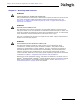
Dialogic® SS7G21 and SS7G22 Signaling Servers Hardware Manual Issue 7 Chapter 1: Warnings and Cautions WARNING QUALIFIED SERVICE TECHNICIAN OPERATIONS: Only a qualified service technician is authorized to remove the Top Cover and to access any of the components inside the product. Before removing the Top Cover, see Section 10.1, “Safety: Before Removing the Top Cover” on page 59 and Chapter 7, “Warnings and Cautions”.
Chapter 1 Warnings and Cautions WARNING IF AC POWER SUPPLIES ARE INSTALLED: MAINS AC POWER DISCONNECT: The AC power cord(s) is considered the mains disconnect for the product and must be readily accessible when installed. If the individual product power cord(s) will not be readily accessible for disconnection then you are responsible for installing an AC power disconnect for the entire rack unit.
Dialogic® SS7G21 and SS7G22 Signaling Servers Hardware Manual Issue 7 WARNING IF DC POWER SUPPLIES ARE INSTALLED: ISOLATION: The product with DC input is to be installed in a Restricted Access Location in accordance with articles 110-16, 110-17 and 110-18 of the National Electric Code, ANSI/NFPA 70. The DC source must be electrically isolated by double or reinforced insulation from any hazardous AC or DC source. The DC source must be capable of providing up to 200 W of continuous power per feed pair.
Chapter 1 Warnings and Cautions Caution Anti-Static Handling Procedures: The product contains Electrostatic Sensitive Devices (ESDs), which may be permanently damaged if incorrectly handled. If modules are removed from the chassis they must be handled in accordance with appropriate anti-static handling procedures. Refer to IEC61340-5-1 Electrostatics - Part 5-1: Protection of electronic devices from electrostatic phenomena - General requirements for further details.
Dialogic® SS7G21 and SS7G22 Signaling Servers Hardware Manual Issue 7 Chapter 2: Introduction 2.1 Purpose This manual addresses the hardware aspects of the Dialogic® SS7G21 and SS7G22 Signaling Servers (hereinafter sometimes referred to collectively as “the SS7G21 and SS7G22 products” and individually as "SS7G21" and "SS7G22," respectively).
Chapter 2 Introduction A list of product variants to which this manual applies can be found in Section 2.11, “Applicability” on page 14. 2.3 Power Supplies An SS7G21 or SS7G22 product can be ordered with one of the following: • • AC-input Power Supply Cage (SS7G21A, SS7G22A) DC-input Power Supply Cage (SS7G21D, SS7G22D) The Power Supply Cage, which is mounted towards the left rear of the chassis, contains the Power Supply Modules.
Dialogic® SS7G21 and SS7G22 Signaling Servers Hardware Manual Issue 7 Depending on the variant, an SS7G21 can contain one of the following: • • Up to three Dialogic® SPCI2S boards, each providing two T1/E1 interfaces and two V.11 serial ports Up to three Dialogic® SPCI4 boards, each board providing four T1/E1 interfaces Each SPCI2S and SPCI4 board supports 4 SS7 links, giving the SS7G21 a maximum capacity of 12 SS7 links.
Chapter 2 Introduction For more information on Dialogic® SS7 products and solutions, visit http://www.dialogic.com/support/helpweb/signaling. 2.11 Applicability This manual applies to the Equipment Types Dialogic® SS7G21 and SS7G22 product variants listed in Table 1: Table 1.
Dialogic® SS7G21 and SS7G22 Signaling Servers Hardware Manual Issue 7 Chapter 3: Product Specification 3.1 DC Power Supply Module The DC Power Supply Module specification is described as follows: • Input topology: Four-terminal DC input power connector for each Power Supply Module. • Connector type: Screw barrier connectors. • Input voltage: -38 to -75 VDC (nominal -48 to -60 VDC) • Maximum input current: 7.
Chapter 3 Product Specification 3.4 PCM Interface The PCM interface specification is described as follows: • Ports: The number of ports depends on the product variant, which determines the type and number of SS7 Signaling Boards included. See Section 2.11, “Applicability” on page 14 for more information. • Data rate: 2048 kbit/s (E1) or 1544 kbit/s (T1) user configurable for each individual port. • Connector type: RJ45. • Pulse shape: ITU-T G.703, AT&T TR62411.
Dialogic® SS7G21 and SS7G22 Signaling Servers Hardware Manual Issue 7 3.7 Serial Port (COM2) The serial interface port specification is described as follows: • Quantity: One; mounted on the rear of the chassis. • Connector: RJ45. • Electrical: RS232. • Signals: TXD, RXD, DSR, DTR, GND. 3.8 Alarm Outputs The alarm outputs specification is described as follows: • Type: Each alarm (Major, Minor, Critical and *Power) is the output of a SPDT relay contact.
Chapter 3 Product Specification alarms is given in the appropriate SS7G2x User Manual. Section 2.10, “Related Information” on page 13 lists the various user manuals. • MNR Alarm LED (amber) When lit continuously, indicates the presence of a minor fault. A minor fault is an error or event that is detected by the unit but has little or no impact on the actual unit’s operation. The full list of minor alarms is given in the appropriate SS7G2x User Manual. Section 2.
Dialogic® SS7G21 and SS7G22 Signaling Servers Hardware Manual Issue 7 3.10 Physical Specifications The physical specifications of the SS7G21 and SS7G22 are described as follows: • Height: 3.45 inches (87.6 mm) • Width: 17.11 inches (434.6 mm) • Depth: 20 inches (508 mm) • Front clearance: 2 inches (76 mm) • Side clearance: 1 inch (25 mm) • Rear clearance: 3.6 inches (92 mm) • Weight: 18.5 Kgm for a fully-loaded system 3.
Chapter 3 Product Specification 20
Dialogic® SS7G21 and SS7G22 Signaling Servers Hardware Manual Issue 7 Chapter 4: Regulatory Specifications and Declarations Topics covered in this chapter include: • • • Specifications Demonstrating Compliance Declarations of the Manufacturer or Importer Essential Compliance Information 4.1 Specifications Demonstrating Compliance 4.1.1 Safety Compliance 4.1.2 USA: Canada: UL Listed to U.S. and Canadian safety standards.
Chapter 4 Regulatory Specifications and Declarations 4.1.3 22 Telecommunications Compliance USA: TIA/EIA-IS-968 – July 2001 (SPCI, therefore SS7G21) TIA-968-A – Oct 2002 (SS7HDP, therefore SS7G22) FCC Part 68 rules as adopted by ACTA, achieved by including interface card(s) with ACTA Product-Labeling number; • US: ICKCNNANSS7SPCI • US: ICKCNNANSS7HDP Interface classified as an “XD” terminal device (T1 DSX-1 type).
Dialogic® SS7G21 and SS7G22 Signaling Servers Hardware Manual Issue 7 4.2 Declarations of the Manufacturer or Importer The International Declarations of Conformity for Dialogic® SS7G21 and SS7G22 products are copied below, or can be downloaded from: http://www.dialogic.com/declarations/ Declaration of Conformity No: D0005 Revision 01 The equipment described below is declared to be in conformity with the following applicable national and international standards.
Chapter 4 Regulatory Specifications and Declarations Declaration of Conformity No: D0006 Revision 01 The equipment described below is declared to be in conformity with the following applicable national and international standards. The conformity is valid ONLY when the equipment is used in a manner consistent with the manufacturer’s recommendations and the reference documents.
Dialogic® SS7G21 and SS7G22 Signaling Servers Hardware Manual Issue 7 4.2.1 CE Declaration of Conformity – European Economic Area The Products carry the CE mark: Hereby, Dialogic Corporation, declares that the Dialogic® SS7G21 and SS7G22 products are in compliance with the essential requirements and other relevant provisions of European Union Directives 1999/5/EC (R&TTE), 89/336/EEC (EMC Directive) and 2006/95/EC (Low Voltage Directive).
Chapter 4 Regulatory Specifications and Declarations [Malti] - tig· jiet essenzjali u ma Hawnhekk, Dialogic Corporation, jiddikjara li dan SS7G21, SS7G22 jikkonforma mal-h provvedimenti oh rajn relevanti li hemm fid-Dirrettiva 1999/5/KE, 89/336/KEE, 2006/95/KE. [Nederlands] Hierbij verklaart Dialogic Corporation dat het toestel SS7G21, SS7G22 in overeenstemming is met de essentiële eisen en de andere relevante bepalingen van richtlijn 1999/5/EG, 89/336/EEG, 2006/95/EG.
Dialogic® SS7G21 and SS7G22 Signaling Servers Hardware Manual Issue 7 A plug and jack used to connect this equipment to the premises wiring and telephone network must comply with the applicable FCC Part 68 rules and requirements adopted by the ACTA. The T1 interface provided on this equipment is classified by the FCC as an “XD” terminal device (T1 DSX-1 type) and must be connected behind a registered CSU or PBX.
Chapter 4 Regulatory Specifications and Declarations 4.3 Essential Compliance Information This section documents miscellaneous points that should be observed to ensure the proper and safe use of this product worldwide. 4.3.1 Safety Users of these products must refer to the safety information included in Chapter 1, “Warnings and Cautions”and Chapter 11, “International Warnings”. Service personnel must also refer to the safety information in Chapter 7, “Warnings and Cautions”, Section 10.
Dialogic® SS7G21 and SS7G22 Signaling Servers Hardware Manual Issue 7 Note that for some geographic regions, and subject to limitations, the T1/E1 ports of SS7HDP boards in SS7G22 products may be connected to “outside plant” signal conductors, and therefore become TNV-1 circuits. If your application needs to use these TNV-1 capabilities, then you must consult the Installation Guide and Regulatory Notices of the SS7HDP for detailed information, including SAFETY WARNINGS, and service instructions.
Chapter 4 Regulatory Specifications and Declarations 30
Dialogic® SS7G21 and SS7G22 Signaling Servers Hardware Manual Issue 7 Chapter 5: Hardware Description 5.1 Overview The Dialogic® SS7G21 and SS7G22 products are equipped with a Server Board containing dual Intel Xeon processors with 512 KB L2 cache and 1 GB DRAM DIMM memory.
Chapter 5 Hardware Description 5.2 Front Panel Figure 3 shows the front panel controls, indicators and switches and Table 3 summarizes their functions. Figure 3. Front Panel Controls, Indicators and Switches Front Bezel Thumb Screws Power Switch CDROM Drive Not Used Reset Switch Alarm LEDs CRT ID System ID NIC Switch LED Activity LED MJR MNR PWR Unused Port ON Disk 1 Disk 0 USB 2 USB 3 LED Activity LED Activity LED Table 3.
Dialogic® SS7G21 and SS7G22 Signaling Servers Hardware Manual Issue 7 5.3 Back Panel Figure 4 shows the back panel connectors and Table 4 summarizes their function. Figure 4.
Chapter 5 Hardware Description 5.4 Rack Mounting Options A number of optional mounting arrangements are available for the Dialogic® SS7G21 and SS7G22 products. The mounting hardware that you order depends on your application. See Chapter 12, “Part Number Reference” for information on selecting the correct mounting hardware. Note: Mounting kits are separately orderable and are not included with the product. Complete installation instructions are included with each mounting kit.
Dialogic® SS7G21 and SS7G22 Signaling Servers Hardware Manual Issue 7 Chapter 6: Interfaces This section provides connector pinout details for all used interface connectors on the SS7G21 and SS7G22. For locations refer to Section 5.3, “Back Panel” on page 33. 6.1 DC Power Input Terminal Block A DC Power Input Terminal Block is provided at the rear of the DC-input Power Supply Cage (DC products only). Connection to a DC power source should be performed only by a qualified service tecnhician.
Chapter 6 Interfaces Figure 6. PCM Ports on SPCI4 Boards T1/E1 Ports L1 L2 L3 L4 Figure 7. PCM Ports on SS7HDP Boards T1/E1 Ports Unused Port ENET L1 L4 The T1/E1 ports on the SS7 Signaling Boards are Safety Extra Low Voltage (SELV), that is, the apparatus connects to the outside network via Network Termination units (NT1). Use twisted-pair, screened cables, grounded at both ends, to ensure the EMC and error-free performance of the product. See also Section 4.3.
Dialogic® SS7G21 and SS7G22 Signaling Servers Hardware Manual Issue 7 Figure 8. SS7 Serial Interface Connector (Aux on SPCI2S) T1/E1 Ports V.11 Ports AUX L3 L4 The SS7 serial interface ports on the SPCI2S are designated as SELV. Install the ferrite clamp(s), provided with this product, on each SS7 serial interface port cable, close to the connector backshell, to ensure the EMC performance of the product. The connector pinout and signal assignment is given in Table 6. Table 6.
Chapter 6 Interfaces An SS7 Serial Interface Port Splitter Cable is available, DKL26 (see Chapter 12, “Part Number Reference”). This is a cable that converts from the dual V.11 26-way high density D connector (detailed in Table 6) to two 15-way male DB15 connectors (detailed in Table 7). When installing this cable, ensure that the ferrite clamp is fitted close to the 26-way connector. Table 7.
Dialogic® SS7G21 and SS7G22 Signaling Servers Hardware Manual Issue 7 Table 8. Ethernet Interface Connector Pinouts Pin No Direction 1 Output TXP 2 Output TXM 3 Input 4 6 RXP Connected to Pin 5 5 6.7 Function Connected to Pin 4 Input RXM 7 GND 8 GND Serial Port (COM2) One serial port (COM2, marked 10101) is provided on the back panel. This is an RS232 port using an 8-way RJ45 connector (see Figure 10). The serial port can be used for configuration and management of the product.
Chapter 6 Interfaces 6.8 Alarms The alarms port interface is a 15-way male DB15 connector (see Figure 11). This connector allows remote notification of alarm conditions. Table 10 shows the alarms connector pinouts. Each alarm (Major, Minor, Critical and Power) is the output of a SPDT relay contact. A common contact with normally open and normally closed connections is included. Power alarm has just a common and normally open contact outputs. The alarms port is designated as SELV.
Dialogic® SS7G21 and SS7G22 Signaling Servers Hardware Manual Issue 7 Part 2: Service Technician’s Guide 41
Dialogic® SS7G21 and SS7G22 Signaling Servers Hardware Manual Issue 7 42
Dialogic® SS7G21 and SS7G22 Signaling Servers Hardware Manual Issue 7 Chapter 7: Warnings and Cautions WARNING QUALIFIED SERVICE TECHNICIAN OPERATIONS: Only a qualified service technician is authorized to remove the Top Cover and to access any of the components inside the product. Before removing the Top Cover, see Section 10.1, “Safety: Before Removing the Top Cover” on page 59 and Chapter 7, “Warnings and Cautions”.
Chapter 7 Warnings and Cautions WARNING IF AC POWER SUPPLIES ARE INSTALLED: MAINS AC POWER DISCONNECT: The AC power cord(s) is considered the mains disconnect for the product and must be readily accessible when installed. If the individual product power cord(s) will not be readily accessible for disconnection then you are responsible for installing an AC power disconnect for the entire rack unit.
Dialogic® SS7G21 and SS7G22 Signaling Servers Hardware Manual Issue 7 WARNING IF DC POWER SUPPLIES ARE INSTALLED: ISOLATION: The product with DC input is to be installed in a Restricted Access Location in accordance with articles 110-16, 110-17 and 110-18 of the National Electric Code, ANSI/NFPA 70. The DC source must be electrically isolated by double or reinforced insulation from any hazardous AC or DC source. The DC source must be capable of providing up to 200 W of continuous power per feed pair.
Chapter 7 Warnings and Cautions Caution Anti-Static Handling Procedures: The product contains Electrostatic Sensitive Devices (ESDs), which may be permanently damaged if incorrectly handled. If modules are removed from the chassis they must be handled in accordance with appropriate anti-static handling procedures. Refer to IEC61340-5-1 Electrostatics - Part 5-1: Protection of electronic devices from electrostatic phenomena - General requirements for further details.
Dialogic® SS7G21 and SS7G22 Signaling Servers Hardware Manual Issue 7 Chapter 8: Tools and Supplies Needed Procedures in Part II of this manual require the following tools and supplies (see Figure 12): • • • • • • Jumper-removal tool or needle-nosed pliers Small flat-bladed screwdriver Phillips (cross-head) screwdriver (#2) Pen or pencil Anti-static wrist strap and conductive foam pad (recommended) Cable tie Figure 12.
Chapter 8 Tools and Supplies Needed 48
Dialogic® SS7G21 and SS7G22 Signaling Servers Hardware Manual Issue 7 Chapter 9: Product Installation and Hot-Swap Actions This chapter describes actions that must be performed by a qualified service technician, but which do not require the removal of the Top Cover of the product. Before commencing these procedures, read Chapter 7, “Warnings and Cautions” in Part II of this manual. Do not proceed to remove the Top Cover without consulting Section 10.
Chapter 9 Product Installation and Hot-Swap Actions — Configure the product. 10. When installation is complete and the system is operating as intended, consider if you will want to install a replacement Hard Disk Drive (HDD) in the future. If you do, now is an ideal time to perform a backup of the System Configuration, which is a necessary step before the HDD can be replaced. For information on how to back up the System Configuration, read the instructions in Section 9.3.
Dialogic® SS7G21 and SS7G22 Signaling Servers Hardware Manual Issue 7 • 9.2.1 Replacement of Power Supply Module in AC Products The general actions required, such as (un)latching, removal and insertion of modules, are described in Section 9.2.6. The connections are unaffected by AC Module replacement. If replacing a failed module, it is possible that the relevant fuse may need replacement. It should be possible to determine if this is necessary from the LED indication on the new module.
Chapter 9 Product Installation and Hot-Swap Actions Figure 13. DC Power Supply Module Terminal Block D Insulating Cover DC Power Supply Module Terminal Block Connections The product is supplied with an insulating cover over the terminal block. To gain access to the terminals, apply gentle pressure to flip up the cover, while using a small flat blade screwdriver to unlatch each side in turn. When the wiring is complete the cover must be flipped down, and securely latched at both sides.
Dialogic® SS7G21 and SS7G22 Signaling Servers Hardware Manual Issue 7 Figure 15. DC Power Terminal Lug When selecting an appropriately sized power wire, consider the power rating of the product, and the length of the cable run. When installing the product in locations other than telecommunications centres, ensure that the cables connecting the DC power input, and the safety ground conductor, are less than 3 metres in length.
Chapter 9 Product Installation and Hot-Swap Actions Note: For DC powered products, the power source should be disconnected from any module while it is being removed or installed. When hot-swap functionality is required, ensure that one module remains installed, connected, and powered at all times. CAUTION 1 Both module positions should have either a Power Supply Module or a filler module installed whenever the product is operational. Otherwise the cooling efficiency of the remaining module is impaired.
Dialogic® SS7G21 and SS7G22 Signaling Servers Hardware Manual Issue 7 Note: For AC powered products, the power source may be connected and turned on during Power Supply Module installation/replacement. When hot-swap functionality is required two AC power cords must be connected. CAUTION 1 Both module positions should have either a Power Supply Module or a filler module installed whenever the product is operational. Otherwise the cooling efficiency of the remaining module is impaired.
Chapter 9 Product Installation and Hot-Swap Actions An SS7G20SHDD may be used in any SS7G2x Signaling Server, however, it requires a valid System License for that system. The process for making a backup of the System License and additional configuration files is described below. Note: Only one hard disk may be used in an SS7G2x at any time. Using more than one may adversely affect system operation. A Hard Disk Drive replacement process occurs in three stages: 1.
Dialogic® SS7G21 and SS7G22 Signaling Servers Hardware Manual Issue 7 Figure 18. Replacing the Hard Disk Drive 2. To unlock the carrier from the chassis, press the green tab on (horizontal) lever to the right to unlock the lever. Rotate lever 90 degrees clockwise to a vertical position, to disconnect the SCSI drive connection. 3. To remove the carrier, press to the right the green latch at the left end of the carrier handle, allowing the handle to swing out, and the carrier to be unlocked.
Chapter 9 Product Installation and Hot-Swap Actions 58
Dialogic® SS7G21 and SS7G22 Signaling Servers Hardware Manual Issue 7 Chapter 10: Working Inside the Product This chapter describes actions that must be performed by a qualified service technician, and which require the removal of the Top Cover from a Dialogic® SS7G21 or SS7G22 product. Before commencing these procedures, read the Chapter 7, “Warnings and Cautions”, the safety advice in Section 10.1, and the warnings and cautions, in Section 10.2. The removal of the Top Cover is described in Section 10.
Chapter 10 Working Inside the Product Caution Electrostatic Discharge (ESD) and ESD Protection: ESD can damage Hard Disk Drives (HDDs), boards, and other parts. We recommend that you do all procedures in this chapter only at an ESD-protected workstation. If one is not available, provide some ESD protection by wearing an anti-static wrist strap attached to chassis ground (any unpainted metal surface) on your product when handling parts. Caution ESD and Board Handling: Always handle boards carefully.
Dialogic® SS7G21 and SS7G22 Signaling Servers Hardware Manual Issue 7 Figure 19. Top Cover Removal and Installation 10.4 Internal Product Layout The layout of the components in the chassis of the Dialogic® SS7G21 or SS7G22 product is shown in Figure 20, and the components are identified in Table 12. Figure 20.
Chapter 10 Working Inside the Product Table 12. Major Components in an SS7G21 and SS7G22 Chassis Label in Figure 20 10.5 Component Name A Power Supply Cage B Signaling Board Subsystem C PCI card bracket (low-profile) D Server Board E PCI NIC (low-profile) F Riser Board assembly (low-profile) G Chassis fans H Hard Disk Drives (HDD) in carriers I CD-ROM Drive SS7 Signaling Boards SS7G21 and SS7G22 are available with up to three SS7 Signaling Boards installed.
Dialogic® SS7G21 and SS7G22 Signaling Servers Hardware Manual Issue 7 Note: If only two SPCI Signaling Boards are installed, then the middle position (No.2) should remain empty. Table 13. Signaling Board Positions and Configurations for SS7G21 Product Variants Quantity of Boards (Variant Suffix) Board Position ADDR Jumpers 1 board (D1W / Q1W) 2 boards (D2W / Q2W) 3 boards (D3W / Q3W) No.
Chapter 10 Working Inside the Product Note: If only two SS7HDP Signaling Boards are installed, then the middle position (No.2) should remain empty. Table 14. Signaling Board Positions and Configurations for Dialogic® SS7G22 Product Variants Quantity of Boards (Variant Suffix) Board Position ADDR 0 boards (00W) 1 board (H1W) 2 boards (H2W) 3 boards (H3W) No.
Dialogic® SS7G21 and SS7G22 Signaling Servers Hardware Manual Issue 7 2. To remove the Signaling Board Subsystem, un-latch it from the chassis by placing your thumb on the rear chassis rail, and your fingers inside the recess at the rear of the Subsystem. A gentle squeeze will then lift the rear part of the Subsystem and release the Riser Board from its connector. The Signalling Board Subsystem can then be simply lifted upward out of the chassis. 3. Loosen the captive screw, and remove the PCI card keep.
Chapter 10 Working Inside the Product Figure 24. Cable Tie Securing SS7 Signaling Board to Card Keep Frame Cable Tie CT Bus Cable Notes Note: When the CT Bus cable is installed, it is important that the two end connectors must be connected to boards. To achieve this consider the following: • For single board systems, the CT Bus cable cannot be connected. For systems delivered as “single board”, the cable is stowed in clips fastened to the underside of the Top Cover.
Dialogic® SS7G21 and SS7G22 Signaling Servers Hardware Manual Issue 7 ADVARSEL Lithiumbatteri - Eksplosjonsfare. Ved utskifting benyttes kun batteri som anbefalt av apparatfabrikanten. Brukt batteri returneres apparatleverandøren. VARNING Explosionsfara vid felaktigt batteribyte. Använd samma batterityp eller en ekvivalent typ som rekommenderas av apparattillverkaren. Kassera använt batteri enligt fabrikantens instruktion. VAROITUS Paristo voi räjähtää, jos se on virheellisesti asennettu.
Chapter 10 Working Inside the Product 68
Dialogic® SS7G21 and SS7G22 Signaling Servers Hardware Manual Issue 7 Chapter 11: International Warnings 11.1 WARNING: English The power supply in this product contains no user-serviceable parts. There may be more than one supply in this product. Refer servicing only to qualified personnel. Do not attempt to modify or use the supplied AC power cord if it is not the exact type required. A product might be equipped with more than one AC power cord.
Chapter 11 International Warnings Warning: English (continued) A microprocessor and heat sink might be hot if the system has been running. Also, there might be sharp pins and edges on some board and chassis parts. Contact should be made with care. Consider wearing protective gloves. Danger of explosion if the battery is incorrectly replaced. Replace only with the same or equivalent type recommended by the equipment manufacturer. Discard used batteries according to manufacturer’s instructions.
Dialogic® SS7G21 and SS7G22 Signaling Servers Hardware Manual Issue 7 11.2 AVERTISSEMENTS: Français Le bloc d'alimentation de ce produit ne contient aucune pièce pouvant être réparée par l'utilisateur. Ce produit peut contenir plusieurs blocs d'alimentation. Veuillez contacter un technicien qualifié en cas de problème. Ne pas essayer d'utiliser ni de modifier le câble d'alimentation CA fourni, s'il ne correspond pas exactement au type requis.
Chapter 11 International Warnings Avertissements : Français (suite) Afin de permettre le refroidissement et l'aération du système, réinstallez toujours les panneaux du châssis avant de mettre le système sous tension. Le fonctionnement du système en l'absence des panneaux risque d'endommager ses pièces. Pour installer les panneaux, procédez comme suit: 1. Assurez-vous ne pas avoir oublié d'outils ou de pièces démontées dans le système. 2.
Dialogic® SS7G21 and SS7G22 Signaling Servers Hardware Manual Issue 7 11.3 WARNUNG: Deutsch Das Netzteil dieses Computers enthält keine wartungsbedürftigen Teile. Dieses Produkt kann über mehrere Netzteile verfügen. Überlassen Sie Wartungsarbeiten nur qualifizierten Fachleuten. Versuchen Sie nicht, das mitgelieferte Netzkabel zu verändern oder einzusetzen, wenn es nicht exakt dem benötigten Kabeltyp entspricht. Das Produkt kann über mehrere Netzkabel verfügen.
Chapter 11 International Warnings Warnung: Deutsch (Fortsetzung) Um eine ordnungsgemäße Kühlung und Belüftung zu gewährleisten, sollten Sie stets die Gehäuseabdeckung anbringen, bevor Sie das System in Betrieb nehmen. Wenn das System ohne obere und vordere Abdeckung betrieben wird, kann es zu einer Beschädigung der Systemkomponenten kommen. So entfernen Sie die Gehäuseabdeckung: 1. Prüfen Sie, daß weder Werkzeuge noch Kleinteile im Innern des Systems vergessen wurden. 2.
Dialogic® SS7G21 and SS7G22 Signaling Servers Hardware Manual Issue 7 11.4 AVVERTENZA: Italiano L'alimentatore contenuto nel computer non contiene parti riparabili dall'utente. Questo prodotto può essere fornito con più alimentatori. Per l'assistenza fare riferimento solo a personale qualificato. Non tentare di modificare o utilizzare cavi di alimentazione in c.a. che non siano del tipo prescritto. Un prodotto potrebbe contenere più di un cavo di alimentazione in c.a.
Chapter 11 International Warnings Avvertenza: Italiano (continua) Per evitare che il sistema si surriscaldi e per garantire una ventilazione adeguata, reinstallare sempre i coperchi prima di attivare il sistema. Se si attiva il sistema senza aver riposizionato i coperchi correttamente, alcune parti del sistema potrebbero risultare danneggiate. Per installare i coperchi: 1. Verificare innanzitutto di non aver lasciato utensili o altre parti all'interno del sistema. 2.
Dialogic® SS7G21 and SS7G22 Signaling Servers Hardware Manual Issue 7 11.5 ADVERTENCIA: Español La fuente de alimentación de este producto no contiene piezas que puedan ser reparadas por el usuario. Puede que haya más de una fuente de alimentación en este producto. Para las reparaciones, consulte sólo con el personal cualificado. No intente modifica ni utilizar el cable de alimentación de CA suministrado si no es del tipo exacto requerido.
Chapter 11 International Warnings Advertencia: Español (continuación) Para obtener una ventilación y un flujo de aire adecuados, reinstale siempre las cubiertas de la carcasa antes de encender el sistema. Si utiliza el sistema sin las cubiertas en su lugar, puede que se dañen algunas piezas del sistema. Para instalar las cubiertas: 1. Asegúrese primero de no haber dejado piezas o herramientas sueltas en el sistema. 2.
Dialogic® SS7G21 and SS7G22 Signaling Servers Hardware Manual Issue 7 Chapter 12: Part Number Reference Table 15 shows the Dialogic® SS7G2x product IDs, operating mode IDs and the supported protocol module IDs. Table 16 gives the product IDs of the expansion options or spare assemblies available for SS7G2x products and Table 17 gives the product IDs of the accessories that can be used with SS7G2x products. Table 15.
Chapter 12 Part Number Reference Table 16. Expansion Options or Spare Assemblies Product ID Description SS7SPCI2SQ SS7 Signaling Board, 4 SS7 links, 2 E1/T1, 2 V.
Dialogic® SS7G21 and SS7G22 Signaling Servers Hardware Manual Issue 7 Chapter 13: Software Licensing Information This chapter gives important information relating to licensed software used by these products. 13.1 Linux Software Distribution This product uses a Linux software distribution. The distribution and full source code can be downloaded from: ftp://archive.download.redhat.com/pub/redhat/linux/9/en/iso/i386 In addition, the rc.local file has been modified and is shown below.
Chapter 13 Software Licensing Information 82
Dialogic® SS7G21 and SS7G22 Signaling Servers Hardware Manual Issue 7 Appendix A A.1 Connecting to V.11 (V.35-Compatible) SS7 Links This appendix discusses the issues of connecting SS7G21 product variants which include SPCI2S boards to a V.35 interface. See the Chapter 12, “Part Number Reference” for the complete list of products variants. Units designated SS7G21ADxW and SS7G21DDxW have SPCI2S boards pre-installed. The V.
Appendix A A.1.2.1 Connecting an SPCI2S to an M34 Block Connector The following table provides information on connecting an SPCI2S (working as a DTE) to a V.35 block connector (working as a DCE). V.
Dialogic® SS7G21 and SS7G22 Signaling Servers Hardware Manual Issue 7 A.1.3 Clocking Physically, the SPCI2S has two sets of clock pins for each serial port. These are designated “Transmit Clock” and “Receive Clock”. The “Transmit Clock” is always an output, while the “Receive Clock” is always an input. The following clocking modes are currently supported: 1. SPCI2S/SIU Generates Clocking In this mode, the “Transmit Clock” signal is driven (at 64kb/s) by the SPCI2S/SIU.
Appendix A 86
Dialogic® SS7G21 and SS7G22 Signaling Servers Hardware Manual Issue 7 Glossary CT Bus A time division multiplex (TDM) bus that provides 1024, 2048, or 4096 time slots for exchanging voice, fax, or other network resources on a PCI (H.100) or CompactPCI (H.110) backplane. The Enterprise Computer Telephony Forum (ECTF) developed the H.100 hardware compatibility specification that defined the CT Bus, a highperformance mezzanine bus.
Glossary 88
Dialogic® SS7G21 and SS7G22 Signaling Servers Hardware Manual Issue 7 Index A AC power supply module hot-swap 55 installation of 8, 50 installing a second unit 12, 50 overcurrent protection 8 power cord 8 power input 35 replacement of 51, 54 specifications 15 accessories list of 80 alarm indicators 17, 32 alarm outputs specifications 17 alarms port connector pinouts 40 location of 40 B backing up the system configuration files backed up 56 battery replacing 66 C cables 28, 38, 80, 83 Cautions for ser
Index G grounding 8, 9, 33, 35, 51 H hard disk drive backing up the system 56 description of 12 location of in chassis 62 replacing the hardware 56 restoring the system configuration 57 hot-swap AC power supply module 12, 55 DC power supply module 12, 52 I Installation 49 L LEDs on back panel 18 on front panel 17 licensing software distribution information 81 M MTBF 19 O options list of 80 order numbers list of 79 P part numbers list of 79 PCI card bracket location in chassis 62 PCI NIC locati
SS7AM1 Programmer’s Manual Issue 7 for SS7 serial interface ports 38 SS7 serial interface port location of 36 see also "V.11 (V.